83
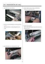
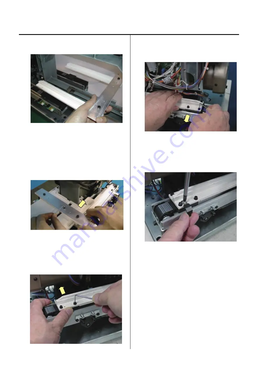
3-6-1 Assemble the arm ass’y
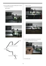
1. Assemble the arm ass’y tentatively.
2. Hold arm to backward and tighten only hithermost
screw.
<Caution>
Make sure that there is clearance between arm and
body.
3. Hold the left side of arm to body and tighten screw.
4. Hold the right side of arm to arrow pointed direction
at below picture and tighten screw.
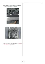
5. Assemble detecting plate.
Make sure that detecting plate is mount perpendicular and
parallel to the arm.
Содержание HCS2-1201-30
Страница 1: ...Maintenance Manual for Embroidery Machine HCS2 1201 30 Version 2 3 HappyJapan Inc...
Страница 75: ...76 6 Check up with thread trimmer function 7 Assemble lower front panel to terminate this procedure...
Страница 110: ...112 3 7 4 Exchange of Y carriage belt 1 Remove frame base 2 Disconnect X carriage cable 3 Remove X carriage 4 Remove arm...
Страница 154: ...153 5 1 1 Electrical connection diagram except for Rev A...
Страница 155: ...154 5 1 1 Electrical connection diagram except for Rev A...
Страница 156: ...155 5 1 2 List of electrical connection diagrams except for Rev A...
Страница 157: ...156 5 1 3 Electrical connection diagram for Rev A...
Страница 158: ...157 5 1 3 Electrical connection diagram for Rev A...
Страница 159: ...158 5 1 4 List of electrical connection diagrams for Rev A...
Страница 160: ...159 5 2 1 Connection of inverter 100V Inverter set...
Страница 161: ...160 5 2 2 Connection of inverter 200V Inverter set...
Страница 165: ...160c HCD8116 TP switch board ass y 6 5 265 2 1 6 7 257...
Страница 196: ...2017 8 HAPPYJAPAN Inc 9 5 TAITO 2 CHOME TAITO KU TOKYO JAPAN TEL 81 3 3834 0711 FAX 81 3 3835 8917...

