18
2
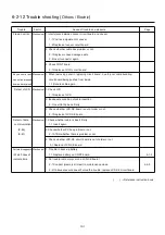
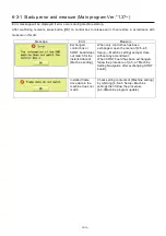
6-3-
2
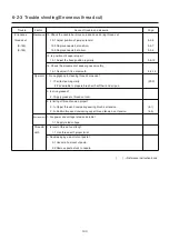
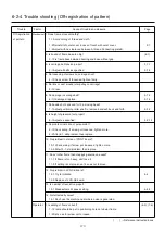
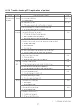
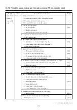
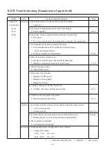
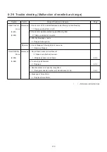
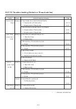
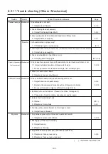
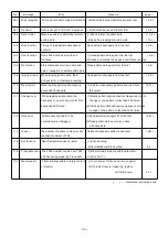
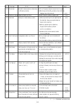
Error and measure
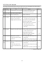
When trouble occurred while the machine is running, error number and error item will be displayed. After confirming contents,
press key [OK] o release error, then restore in accordance with measure in this list.
No. Message Error Measure Page
001 Circuit board Trouble detected in control circuit board. (1)Turn power off once and turn on again.
(2)If recurred, replace LCD-CE board. 4-1-1
002 Power source Power failure or abnormal voltage
004 System memory Trouble in system memory. Replace LCD-CE board. 4-1-1
015 Inverter trip Trouble in drive unit on main shaft. (1)Turn power off, turn main shaft by hand and
Overload on main shaft motor, if no trouble found, turn power on again.
damage in drive unit on main shaft. (2)If trouble found, repair where damaged.
(3)If inverter in trouble, replace. 4-3
(4)Check if voltage high or not. If high,check
origin of power source of factory.
Or use stabilizer, transformer to set to
rated voltage.
018 Main shaft Suspension of main shaft in mid way. (1)Check if trouble found between main shaft
and drive. If trouble found, restore.
(2)If recurred, find cause and fix.
(3)Make automatic speed setting again. 4-4-5
(4)If inverter in trouble, replace. 4-3
020 Needle detect Needle position not detected. (1)Turn needle selection cam by hand to set to
Trouble in stop position of needle regular position.
selection unit. (2)Fix needle selection related mechanical trouble.
(3) Replace sensor circuit board or potentiometer. 4-2-4
021 Needle move Suspension of needle selection motor (1)Turn needle selection cam by hand to set to
022 in mid way. regular position.
Trouble in take-up lever hinders. (2)Fix needle selection related and take up lever
Trouble in position detecting circuit related troubles.
board. (3)Replace sensor circuit board or potentiometer. 4-2-4
( ) ----- Reference instruction book
Содержание HCS2-1201-30
Страница 1: ...Maintenance Manual for Embroidery Machine HCS2 1201 30 Version 2 3 HappyJapan Inc...
Страница 75: ...76 6 Check up with thread trimmer function 7 Assemble lower front panel to terminate this procedure...
Страница 110: ...112 3 7 4 Exchange of Y carriage belt 1 Remove frame base 2 Disconnect X carriage cable 3 Remove X carriage 4 Remove arm...
Страница 154: ...153 5 1 1 Electrical connection diagram except for Rev A...
Страница 155: ...154 5 1 1 Electrical connection diagram except for Rev A...
Страница 156: ...155 5 1 2 List of electrical connection diagrams except for Rev A...
Страница 157: ...156 5 1 3 Electrical connection diagram for Rev A...
Страница 158: ...157 5 1 3 Electrical connection diagram for Rev A...
Страница 159: ...158 5 1 4 List of electrical connection diagrams for Rev A...
Страница 160: ...159 5 2 1 Connection of inverter 100V Inverter set...
Страница 161: ...160 5 2 2 Connection of inverter 200V Inverter set...
Страница 165: ...160c HCD8116 TP switch board ass y 6 5 265 2 1 6 7 257...
Страница 196: ...2017 8 HAPPYJAPAN Inc 9 5 TAITO 2 CHOME TAITO KU TOKYO JAPAN TEL 81 3 3834 0711 FAX 81 3 3835 8917...

