3
7
3-2-8
Adjustment of take-up lever timing
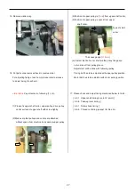
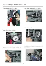
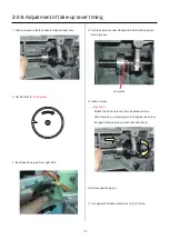
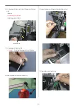
1. Loosen screw on fasten collar for take-up lever cam.
2. Set dial disc to
[10 degrees]
.
3. Insert positioning pin from right side.
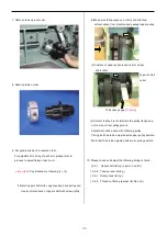
4. Turn take up lever cam slowly and insert positioning pin
into pin groove.
pin groove
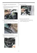
5. Loosen screw.
<Important>
Rotate the Take up lever cam clockwise until pin
ditch touches to positioning pin then tighten the screw.
(No gap between take-up lever cam and crank)
6. Pull out positioning pin.
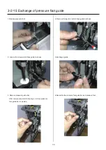
7. Turn upper shaft and set dial disc to [
C
] to finish.
Содержание HCS2-1201-30
Страница 1: ...Maintenance Manual for Embroidery Machine HCS2 1201 30 Version 2 3 HappyJapan Inc...
Страница 75: ...76 6 Check up with thread trimmer function 7 Assemble lower front panel to terminate this procedure...
Страница 110: ...112 3 7 4 Exchange of Y carriage belt 1 Remove frame base 2 Disconnect X carriage cable 3 Remove X carriage 4 Remove arm...
Страница 154: ...153 5 1 1 Electrical connection diagram except for Rev A...
Страница 155: ...154 5 1 1 Electrical connection diagram except for Rev A...
Страница 156: ...155 5 1 2 List of electrical connection diagrams except for Rev A...
Страница 157: ...156 5 1 3 Electrical connection diagram for Rev A...
Страница 158: ...157 5 1 3 Electrical connection diagram for Rev A...
Страница 159: ...158 5 1 4 List of electrical connection diagrams for Rev A...
Страница 160: ...159 5 2 1 Connection of inverter 100V Inverter set...
Страница 161: ...160 5 2 2 Connection of inverter 200V Inverter set...
Страница 165: ...160c HCD8116 TP switch board ass y 6 5 265 2 1 6 7 257...
Страница 196: ...2017 8 HAPPYJAPAN Inc 9 5 TAITO 2 CHOME TAITO KU TOKYO JAPAN TEL 81 3 3834 0711 FAX 81 3 3835 8917...


