HAMWORTHY HEATING LTD
1
SPETISBURY
500001118/C
1.0 INTRODUCTION
1.1
The Spetisbury boiler range consists of 5 gas
fired cast iron sectional boilers with outputs ranging
from 110kW to 340kW.
Spetisbury boilers can be used individually, or in a
multi-boiler configuration, and are suitable for use
on either open-vented or sealed low temperature hot
water heating systems. For hot water production
they can be used in conjunction with calorifiers or
indirect hot water cylinders.
Stacking kits are available for pairs of Spetisbury
boilers and are assembled on site to HHL
instructions 500005091 in combination with this
manual.
Portland and Weymouth pressurisation units are
available from Hamworthy Heating Ltd for sealed
systems.
1.2
Spetisbury sectional boilers are supplied
unassembled ready for on-site assembly.
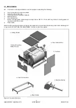
The heat exchanger consists of:
a.
A front section
b.
Plain intermediate sections which can be
adapted to form the 3 types of intermediate
sections.
c.
A rear section
These sections are connected to each other using
guide rings and 'O' ring gaskets and are held
together by short lacing bolts. The complete
assembly is held together by four M14 threaded tie
rods running the length of the heat exchanger.
The section to section flue gas seal is made by:
d.
A mastic strip around the outer perimeter of
each section.
e.
A mastic strip around the perimeter of the
combustion chamber of each section.
The sections are cast with extended surface fins to
increase the heat exchange area and thus enhance
thermal efficiency in use.
The heat exchanger assembly is completed by cast
iron front and rear combustion chamber plates and
access plates for the cleaning and inspection of the
heat exchanger flue ways (on front and rear), all of
which are internally lined with a ceramic fibre
insulation board. The smoke box/flue connector is
bolted to the upper part of the rear section and
sealed with a ceramic fibre gasket.
The heat exchanger is mounted on a steel cradle
which in turn stands on legs, leaving access for
cleaning beneath the heat exchanger. The flow and
return water connections are located at the rear of
the boiler. Refer to Section 8 for details of water
circulation system.
All site wiring is made direct to the burner, refer to
section 10.6 for guidance.
The boiler is housed in a powder coated sheet steel
casing which is supplied flat-packed for on-site
assembly. Refer to Section 10.5 for casing
assembly procedure.
1.3
All Spetisbury boiler sections are hydraulically
tested to 10 bar (145 psi), ensuring the Spetisbury
boiler is suitable for use on systems with maximum
working pressures of up to 5 bar (73 psi).
Содержание Spetisbury
Страница 30: ...HAMWORTHY HEATING LTD 24 SPETISBURY 500001118 C Figure 12 2 Fault Finding Flowchart...
Страница 36: ...HAMWORTHY HEATING LTD 30 SPETISBURY 500001118 C Figure 15 1 Boiler Installation Typical 15 0 TECHNICAL DATA...
Страница 42: ...HAMWORTHY HEATING LTD 36 SPETISBURY 500001118 C NOTES...
Страница 43: ...Notes...


