HAMWORTHY HEATING LTD
SPETISBURY
500001118/C
iii
9.0 SUPPLY TO BURNER
.......................................................................................................................
8
9.1 Electrical installation to Burner
9.2 Gas Train Installation to Burner
10.0 BOILER ASSEMBLY AND INSTALLATION
.....................................................................................
9
10.1 General
10.2 Preparation
10.3 Assembly of Sections
10.4 Assembly of Boiler
10.5 Casing Assembly
10.6 Burner Control and Adjustment
11.0 COMMISSIONING AND TESTING
..................................................................................................
21
11.1 Electrical Installation
11.2 Gas Installation
11.3 Water Circulation System
11.4 Commissioning the Boiler
11.5 External Controls
11.6 Installation Noise
11.7 User Instructions
12.0 FAULT FINDING
..............................................................................................................................
23
13.0 SERVICING
......................................................................................................................................
25
14.0 REPLACEMENT OF FAILED COMPONENTS & RECOMMENDED SPARES
..............................
26
15.0 TECHNICAL DATA AND GENERAL INFORMATION
....................................................................
30
FIGURES PAGE
Figure 2.1 General Overview .....................................................................................................................2
Figure 7.1 Mechanical Ventilation Flow Rates ..........................................................................................6
Figure 8.3 Cold Feed and Vent Pipe Sizes ...................................................................................................7
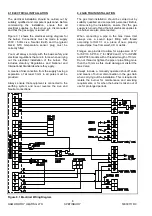
Figure 9.1 Electrical Wiring Diagram ............................................................................................................8
Figure 10.1 Composition of Sections Within Heat Exchanger ..........................................................................9
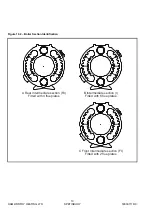
Figure 10.2 Boiler Section Identification .......................................................................................................10
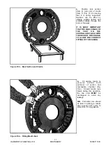
Figure 10.3 Rear Section and Cradle ...........................................................................................................11
Figure 10.4 Fitting Mastic Seal ....................................................................................................................11
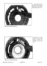
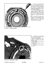
Figure 10.5 Fitting Guide Ring .....................................................................................................................12
Figure 10.6 Fitting ‘O’ Ring Seal ..................................................................................................................12
Figure 10.7 Fitting the Lacing Bolts ..............................................................................................................13
Figure 10.8 Fitting Upper Tie Rods ..............................................................................................................13
Figure 10.9 Fitting Lower Tie Rods ..............................................................................................................14
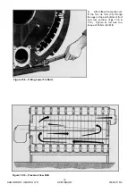
Figure 10.10 Flue Gas Flow Path ..................................................................................................................14
Figure 10.11 Outflow Pipework Orientation ....................................................................................................15
Figure 10.12 Fitting Casing Support Brackets ................................................................................................15
Figure 10.13 Boiler Casing Assembly ............................................................................................................16
Figure 10.14 Boiler Casing Assembly ............................................................................................................16
Figure 10.15 Boiler Casing Assembly ............................................................................................................16
Figure 10.16 Boiler Casing Assembly ............................................................................................................17
Figure 10.17 Boiler Casing Assembly ............................................................................................................17
Figure 10.18 Boiler Casing Assembly ............................................................................................................17
Figure 10.19 Boiler Casing Assembly ............................................................................................................18
Figure 10.20 Boiler Casing Assembly ............................................................................................................18
Figure 10.21 Boiler Casing Assembly ............................................................................................................18
Figure 10.22 Burner Display Panel ................................................................................................................19
Figure 10.23 Throttle and Gas Valve Adjustment Diagram .............................................................................20
Содержание Spetisbury
Страница 30: ...HAMWORTHY HEATING LTD 24 SPETISBURY 500001118 C Figure 12 2 Fault Finding Flowchart...
Страница 36: ...HAMWORTHY HEATING LTD 30 SPETISBURY 500001118 C Figure 15 1 Boiler Installation Typical 15 0 TECHNICAL DATA...
Страница 42: ...HAMWORTHY HEATING LTD 36 SPETISBURY 500001118 C NOTES...
Страница 43: ...Notes...


