HAMWORTHY HEATING LTD
8
SPETISBURY
500001118/C
9.1 ELECTRICAL INSTALLATION
The electrical installation should be carried out by
suitably qualified and competent personnel. Before
commencing the installation, ensure that all
electrical supplies to the burner are disconnected
and that the gas supply is turned off.
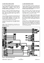
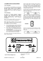
Figure 9.1 shows the electrical wiring diagram for
the burner. Connections must be made to supply
230V / 50Hz Live, Neutral, Earth and the (green/
black) NTC temperature sensor plug must be
correctly fitted.
You must always comply with the basic safety and
electrical regulations that are in force when carrying
out the electrical installation of the burner. This
includes statutory Regulations and National and
International Standards where they apply.
A means of disconnection from the supply having a
separation of at least 3mm in all poles must be
provided.
Always ensure that equipment is connected to the
earthing system and never reverse the Live and
Neutral connections.
9.2 GAS TRAIN INSTALLATION
The gas train installation should be carried out by
suitably qualified and competent personnel. Before
commencing the installation, ensure that the gas
supply is turned off and that all electrical supplies to
the burner are also disconnected.
When connecting a pipe to the Gas Valve Inlet
always use a sound taper fitting with thread
according to ISO 7-1 or a piece of new, properly
reamed pipe, free from swarf, dirt or debris.
Flanges are provided to allow for a pipe size of ¾”
for SP110, SP150, 1” for SP220 and 1¼” for SP280
and SP340 models with a threaded length of 13mm.
Do not thread or tighten the pipe or pipe fitting more
than the 13mm as this could damage or distort the
Gas Valve.
Always include a manually operated shut-off valve
and means of burner disconnection in the gas train
when carrying out the installation. This is required to
isolate the burner for maintenance and servicing
requirements, or for when the burner is taken out of
use for prolonged periods.
Figure 9.1 Electrical Wiring Diagram
Содержание Spetisbury
Страница 30: ...HAMWORTHY HEATING LTD 24 SPETISBURY 500001118 C Figure 12 2 Fault Finding Flowchart...
Страница 36: ...HAMWORTHY HEATING LTD 30 SPETISBURY 500001118 C Figure 15 1 Boiler Installation Typical 15 0 TECHNICAL DATA...
Страница 42: ...HAMWORTHY HEATING LTD 36 SPETISBURY 500001118 C NOTES...
Страница 43: ...Notes...


