HAMWORTHY HEATING LTD
22
SPETISBURY
500001118/C
b.
Check burner seats correctly onto burner
mounting plate and is securely fastened in place.
c.
Open main isolating valve in gas supply to boiler.
Check for leaks throughout gas train and pipework
to boiler.
d.
Adjust gas supply governor to achieve at least
17.5 mbar (7.0 in wg) at inlet to boiler gas train.
Ensure that maximum pressure of gas train
governor is not exceeded. If a gas booster is to be
fitted, commission in accordance with the
manufacturer’s instructions.
e.
Close main isolating valve in gas supply and start
the burner. The burner control will first operate the
fan to pre-purge the boiler, then produce an ignition
spark and attempt to ignite the burner. The flame
should fail to ignite and the burner should go to
lockout after three failed ignition attempts.
f.
Open main isolating valve in gas supply. Reset
the burner control and restart the burner, the main
flame should light at the ignition rate and stabilise
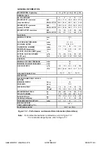
for 90 seconds before running up to full rate. Note:
the fan speed for start, max/min run is factory set
and does not need adjustment (refer to fig 15.7).
g.
After allowing burner to reach stable firing
conditions for approximately 15 minutes, carry out
combustion gas check.
Measure gas pressure at the burner inlet CO
2
, CO,
flue gas temperature, and circulating water
temperature rise across the boiler. The readings
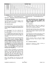
obtained for the appropriate gas should be as
indicated in figure 11.1, target appliance readings.
Readings should be taken at max and min firing
rates. Check and adjust parameters to comply with
target figures nominated in section 10.6 of this
manual.
IF BURNER REPEATEDLY FAILS TO LIGHT, A
FULL INVESTIGATION TO FIND CAUSE SHOULD
BE MADE.
h.
Check gas flow rate at meter. Ensure that all
other appliances served by the meter are isolated
whilst flow rate is checked.
j.
Cycle boiler on and off several times to ensure
reliable burner ignition and boiler operation. Check
for gas, water and flue gas leakage. Tighten all
access, flue box and burner mounting bolts and
nuts.
k.
Set boiler control thermostat to required setting,
and check operation of heating control system.
l.
Fully familiarise the user with the boiler operating
controls, the main component functions and the
safety features.
THESE INSTALLATION AND SERVICING
INSTRUCTIONS SHOULD BE LEFT WITH THE
USER OF THE BOILER FOR FUTURE
REFERENCE.
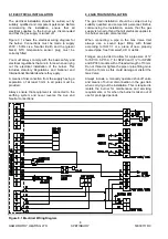
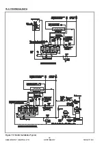
11.5 External Controls
The external controls used in typical boiler
installations, for both vented and unvented systems,
are shown in Figure 15.1. If different systems or
controls are to be used and there are any doubts as
to the suitability, contact Hamworthy Heating
Technical Department for advice.
11.6 Installation Noise
I
n order to avoid the possibility of noise from the
installation, care should be taken to follow the
manufacturer’s instructions. Particular attention should
be paid to minimum water flow rates. If acoustic
insulation is added to the boiler, care must be taken not
to impede combustion or ventilation air flow. If in doubt
contact the manufacturer.
11.7 User Instructions
When the above is complete, the boiler owner or their
representative should be made aware of the lighting
and operating instructions . A practical demonstration
should be given describing each functional step. This
Installer's Guide should then be handed over and kept
in a safe place for easy reference.
Содержание Spetisbury
Страница 30: ...HAMWORTHY HEATING LTD 24 SPETISBURY 500001118 C Figure 12 2 Fault Finding Flowchart...
Страница 36: ...HAMWORTHY HEATING LTD 30 SPETISBURY 500001118 C Figure 15 1 Boiler Installation Typical 15 0 TECHNICAL DATA...
Страница 42: ...HAMWORTHY HEATING LTD 36 SPETISBURY 500001118 C NOTES...
Страница 43: ...Notes...

