HAMWORTHY HEATING LTD
25
SPETISBURY
500001118/C
13.0 SERVICING & MAINTENANCE
A qualified engineer registered for working on non
domestic gas or oil appliances should check and ensure
that the flue, its support and terminal, the ventilation to
the boiler house, safety valve, drain, water filter if fitted,
pressure gauge, etc.; are in a serviceable and working
condition and still comply with the relevant standards
and codes of practice - see
Section 3.1
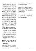
The boiler should be serviced at regular intervals,
not exceeding TWELVE months. In the case of
continuous operation, the maintenance operations
should be carried out every SIX months.
When carrying out boiler servicing always
consider both your own safety and that of
others. The use of protective equipment (e.g.
eye protection, face mask, protective gloves,
etc.) is recommended where necessary.
13.1 Initial Inspection
a.
Operate boiler and check for any signs of
unsatisfactory operation, water leaks, gas leaks or
unusual noise from burner.
b.
After allowing burner to reach stable firing
conditions for approximately 15 minutes, carry out
combustion gas check.
Measure CO
2
, CO, flue gas temperature and water
temperature rise across the boiler. The readings
obtained should be noted for reference upon
completion of the servicing procedure.
c.
Measure gas pressure at inlet to burner gas
train.
d.
Check operation of both boiler and heating
system controls, then set burner to OFF.
Allow the boiler/burner to cool.
13.2 Burner Service Procedure.
SWITCH OFF ELECTRICAL SUPPLY AND FUEL
SUPPLY TO BOILER.
a. Disconnect electrical and fuel connections to
burner.
b.
Disconnect burner from mounting flange and
remove from front of boiler (taking care to remove
thermostat bulbs).
c.
Check the burner head for any signs of
damage or degrading of the material. Cleaning
should only be done using a soft bristle brush and
vacuum cleaner.
d.
Examine the condition of the electrodes and
check that they are clean, undamaged, and not
loose. If necessary, remove, clean using a very fine
emery paper and then refit. For the correct spark
gap and position of the electrodes, refer to Fig. 11.2
In this manual.
e.
Examine all gasket material and check for any
signs of damage or degrading. If necessary, replace
them, but always use the correct type.
f.
Check all electrical connections and cables to
ensure that they are all sound, undamaged and
have not worked loose.
g.
Remove and clean the flexible tube to the air
pressure switch and check that this is functioning
correctly.
h.
If required, clean the combustion air fan.
i.
Refit all parts and reconnect the electricity
and gas supplies.
j.
Check for gas soundness and electrical safety
before switching on.
k.
Switch on the burner and check for correct
operation.
l.
Check combustion CO and CO
2
, levels at
both the minimum and maximum fan speeds as
described in Section 10.6 and adjust if necessary.
IF IT IS NECESSARY TO REPLACE ANY PARTS,
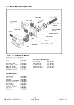
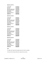
REFER TO SECTION 14.2 OF THIS MANUAL FOR
CORRECT PART NUMBERS.
13.3 Boiler Service Procedure
a
. After removing burner, remove boiler casing
and front insulation to gain access to front section of
boiler.
b
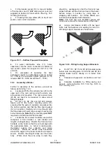
. Remove heat exchanger access plates (11,
12 and 15 referring to Fig. 14.1), and corresponding
insulation panels, from boiler front section.
Boiler combustion chamber and heat exchanger
flueways are now accessible for cleaning with
suitable brushes and a vacuum cleaner.
c
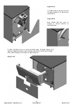
. Access to rear of heat exchanger flueways
and combustion chamber can be obtained by
removing rear insulation wrap, flue box (Fig. 14.1
item 31), cover plate (Fig 14.1 item 32), insulation
and fire brick (Fig. 14.1 item 28) from rear of boiler.
The refractory fire brick (Fig. 14.1 item 28), located
at the rear of the boiler, should be checked at least
once every two years and replaced if necessary.
N.B.
Removal of flue box requires disconnection of
flue.
d
. Replace all access/cover plates, ensuring
that all gaskets and insulation panels are correctly
fitted.
Refit securing studs/nuts and tighten evenly.
e
. Refit boiler insulation and casing. For
guidance, refer to
Section 10.
f
. Refit burner. Reconnect fuel and electrical
supplies. Refit and ensure thermostat bulbs are
correctly located in pocket.
g
. Turn on fuel supply and check soundness of
fuel supply pipework.
h
. Check all flue joints for integrity.
i
. Check ventilation ducts/grilles to boiler room
and ensure they are clear.
j
. Re-commission boiler as detailed in relevant
parts of
Section 11.0: COMMISSIONING & TESTING
Содержание Spetisbury
Страница 30: ...HAMWORTHY HEATING LTD 24 SPETISBURY 500001118 C Figure 12 2 Fault Finding Flowchart...
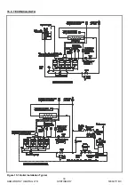
Страница 36: ...HAMWORTHY HEATING LTD 30 SPETISBURY 500001118 C Figure 15 1 Boiler Installation Typical 15 0 TECHNICAL DATA...
Страница 42: ...HAMWORTHY HEATING LTD 36 SPETISBURY 500001118 C NOTES...
Страница 43: ...Notes...

