background image

Read carefully before Installation and Maintenance

CAUTION!

Observe the safety instructions of this installation and 

maintenance manual before placing the boiler in 

operation.

DANGER!

If installation, adjustment, modification, operation or 

maintenance of the heating system is carried out by an 

unqualified person, this may result in danger to life and 

limb or property damage.

The directions of this installation and maintenance 

manual must be followed precisely.

For assistance or additional information consult a 

qualified installer, service agency or the gas supplier.

DANGER!

Caution!The operating manual is a component of the 

technical documentation and must be handed over to 

the operator of the heating system.

Discuss the content of this manual with the owner or 

operator of the heating system to ensure that they are 

familiar with all information required for operation of 

the heating system.

If the storage tank will be installed in Massachusetts, it 

must be installed by an installer or dealer who is 

registered there.

Installation and Service Instructions

Gas condensing boiler

Logano plus GB312

6 720 806 275-00.1T

6 720 806 273 (2013/01) (US/CA)-en

Содержание Logano plus GB312

Страница 1: ...or additional information consult a qualified installer service agency or the gas supplier DANGER Caution The operating manual is a component of the technical documentation and must be handed over to the operator of the heating system Discuss the content of this manual with the owner or operator of the heating system to ensure that they are familiar with all information required for operation of t...

Страница 2: ... 25 6 9 7 Installing the condensate drain 25 6 10 Filling heating system and checking for leaks 26 6 11 Providing the fuel supply 27 6 11 1 Installing gas feed 27 6 11 2 Installation at high altitudes 28 6 12 Electrical connections 29 6 12 1 Connecting the power supply 29 6 12 2 Leveling the boiler 30 7 Placing the heating system in operation 31 7 1 Checking heating system operating pressure 31 7 ...

Страница 3: ...ing the burner and heat exchanger 43 9 7 Checking gas valve for leaks 47 9 8 Checking for leaks during normal operation 48 9 9 Check ionization current 48 9 10 Completing inspection or maintenance 48 9 10 1 Removing instruments 48 9 10 2 Installing jacket panels 48 9 10 3 Confirming inspection or maintenance 48 9 11 Servicing and maintenance logs 49 10 Troubleshooting 51 10 1 Identifying operating...

Страница 4: ... Dangers posed by explosive and easily combustible materials Never use or store easily flammable materials paper curtains clothing thinners paints etc near the boiler Maintain a clearance of 16 inches from the boiler Combustion air Keep the combustion air free of corrosive substances e g halogenated hydrocarbons that contain chlorine or fluorine compounds In that way corrosion will be prevented Da...

Страница 5: ...thesafeandappropriateinstallation commissioningand servicing of this gas condensing boilerLogano plus GB312 The installation and maintenance manual is provided for contractors who have been trained and have experience in working with heating systems and oil fired installations The boiler can be equipped with a user interface e g RC35 accessory Use the boiler only in the combinations and with the a...

Страница 6: ...inacrawlspaceoranattic thehard wiredcarbon monoxide detector with alarm and battery back up may be installed on the next adjacent floor level b Intheeventthattherequirementsofthissectioncannotbemetatthe time of installation the owner shall have a period of thirty 30 days to comply with the above requirements The prerequisite for this is the installation of a battery powered carbon monoxide detecto...

Страница 7: ...iciency are equally important objectives for us Environmental protection laws and regulations are strictly adhered to Toprotecttheenvironment weusethebestpossibletechnologyand materials taking into account economic points of view Packaging For the packaging we participate in the country specific recycling systems which guarantee optimal recycling All packaging materials used are environmentally fr...

Страница 8: ...dasstandard notfactory installed 11 Mating flange 2 included in B kit not factory installed 12 Bolts washers lock washers and nuts to mount supply manifold and mating flanges The main components of the Logano plus GB312 Fig 1 are Controller Frame and jacket Boiler block with insulation Gas burner B kit standard B kit comprising temperature pressure gauge pressure relief valve supply manifold suppl...

Страница 9: ... Many other functions for the convenient control of your heating system are available with a user interface e g RC35 sold separately 2 9 Scope of delivery The Logano plus GB312 is supplied as standard with a Logamatic BC10 basic control unit and the MC10 control unit Upon receipt check that all packaging is in perfect condition Check that all package contents are present Dispose of packaging in an...

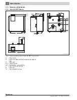
Страница 10: ...dimensions Fig 3 Connections and dimensions for Logano plus GB312 sizes in inches AA Flue connection AL Combustion air pipe connection sealed combustion operation only VK Boiler supply AKO Condensate outlet GAS Gas connection main shutoff valve ST Pressure relief valve connection RK Boiler return TM Pressure temperature gauge ...

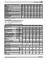
Страница 11: ... min load Btu hr 132 200 132 200 176 500 219 800 264 200 308 600 I B R gross output 180 80 F max load Btu hr 305 000 409 000 544 000 676 000 810 000 944 000 I B R net rating 180 80 F max load Btu hr 265 000 356 000 473 000 588 000 704 000 821 000 Rated heat output 122 86 F max load Btu hr 307 100 409 500 545 900 682 400 819 000 955 400 50 30 C min load Btu hr 128 100 127 400 171 200 212 300 255 20...

Страница 12: ...70 370 min load W 40 40 45 50 50 50 Maximum permissible fuse rating A 10 10 10 10 10 10 Boiler dimensions and weight Transport clearance dimensions width x depth x height Inch 34x25x60 34x25x60 42x25x60 42x25x60 50x25x60 50x25x60 Weight lbs 455 455 530 585 665 730 Boiler size output no of heat exchanger sections Unit 90 4 120 4 160 5 200 6 240 7 280 8 Table 4 Specifications 0 1 1 10 100 1 10 100 1...

Страница 13: ... Lifting the boiler off the pallet 1 Locking screw 2 Pallet Push the pipes through the holes at the front and rear of the boiler Fig 7 page 14 Secure the pipes at the positions shown in Fig 7 to prevent slipping for example by using adhesive tape Carry the boiler to the installation site CAUTION Risk of system damage from impacts The standard boiler includes parts that are sensitive to impact Ifth...

Страница 14: ...the bottom plate is not pressed in it is essential to ensure that the weight is evenly distributed across the load bearing parts 7 747 010 720 07 1RS 7 747 010 720 08 1RS WARNING Risk of system damage due to freezing Install the heating system in a frost free room DANGER Dangers posed by explosive and easily combustible materials Neveruseorstoreeasilyflammablematerials paper curtains clothing thin...

Страница 15: ...uate openings for combustion air and venting of the installation room The openings for combustion air supply and venting are always required regardless of whether the combustion air is supplied from the room operation from room air or directly to the boiler through ducts operation independent of room air Inadequate venting of the installation room may result in excessive ambient temperatures This ...

Страница 16: ... of the total burner output of all gas fired appliances inside the closed room If there is a connection to the outside through a ventilated attic and ventilated crawl space each opening must have a minimum cross section of one square inch per 4000 Btu h of the total burner output of all gas fired appliances inside the closed room The attic must be ventilated at both ends of the house 6 Installing ...

Страница 17: ...le 7 8 or 9 DANGER Risk of fatal injury from escaping flue gases in the installation room The gasket in the flue connector of the condensate pan must be present in good order and correctly inserted Installing an air inlet flap in the flue system is not permitted CAUTION Risk of system damage due to inadequate condensate drainage Use a suitable siphon to drain condensate that accumulates in the flu...

Страница 18: ...ure you observe the safety instructions The wall exit must be installed in accordance with the specified regulations and or local building code regulations Fig 12 Specified clearances to ANSI Z223 1 for horizontal flues A Minimumhorizontaldistancefromairintakeofanotherappliance 10 ft minimum distance from own air intake for directly vented appliances 4 ft B Minimum vertical distance from air intak...

Страница 19: ...anel if not already removed Unscrew the cover plate from the rear panel Attach the 90 elbow on the air supply system to the air inlet connection through the rear panel and seal Construct the air supply pipe using a standard air pipe system according to the national requirements We recommend installing a safety mesh bird screen on the air intake opening For details of correct dimensioning contact t...

Страница 20: ... detailed or illustrated in Fig 12 and Fig 16 should be seen as the absolute minimum and may in some circumstances not be adequate for specific installations Fig 16 Design of air pipe wall penetration A Minimum vertical distance from air intake of another appliance 3 ft with directly vented appliances the flue outlet can be positioned level with the appliance s own air intake observe minimum horiz...

Страница 21: ...boiler systems must be installed according to the specifications of ANSI Z223 1 The clearances detailed or illustrated in Fig 14 and Fig 17 should be seen as the absolute minimum and may in some circumstances not be adequate for specific installations Fig 17 Design of air pipe roof penetration A Minimumhorizontaldistancefromairintakeofanotherappliance 10 ft minimum distance from own air intake for...

Страница 22: ...elbow facing vertically downwards 4 External wall 5 T piece with siphon to drain condensate Fig 20 Air supply and flue outlet on the roof 1 Flue outlet type of outlet depends on chosen manufacturer e g 90 elbow or T piece observe clearances specified in Fig 17 2 Air inlet terminal 90 elbow pointing away from flue outlet 3 Roof 4 T piece with siphon to drain condensate Fig 21 Air supply on the roof...

Страница 23: ...e refrigerant fluid are connected in parallel with the boiler system by means of suitable valves to prevent the refrigerant from entering the boiler The piping system of a boiler connected to the heating coils of hot air heating systems that may be exposedtothecirculationofcooledairmustbefitted with a flow control valve or some other automatic system for preventing the boiler water from circulatin...

Страница 24: ...PT 10 Pressure relief valve safety valve 11 Pressure temperature gauge CAUTION Risk of system damage due to leaking connections Connect system pipes without stress to the boiler connections Boiler Boiler supply VK Boiler return RK 90 4 to 280 8 NPT 2 Table 11 Water connection sizes CAUTION Risk of system damage due to an incorrectly installed B kit or failure to install check valve Make sure that ...

Страница 25: ...Boiler and Pressure Vessel Code Section IV We recommend installing a water filter Y strainer accessory externally to the boiler return RK on site to prevent contamination of the boiler by the water Observe the local regulations for connection of boiler systems DANGER Risk of fire from flammable materials or liquids Do not store flammable materials or liquids in the immediate vicinity of pipes that...

Страница 26: ...lume of 1 gallon of Protek 922 to 25 gallons of system volume Carry out a leak test in accordance with local authority having jurisdiction regulations Fig 28 Pressure temperature gauge A condensate neutralizer is available as an accessory Installtheneutralizingsysteminaccordancewiththe installation instructions Install the trap supplied to the condensate pan drain outlet Condensate may possibly es...

Страница 27: ...s and Safety Devices for Automatically Fired Boilers ASME CSD 1 Accessories to comply with ASME CSD 1 are available please see page 84 and 65 in parts list CAUTION Riskofsystemdamagefromexcessivelyhigh temperatures If you fill the heating system when it is hot the resulting thermal stresses can cause stress cracks The boiler will then leak Fill the heating system only when it is cold the supplytem...

Страница 28: ...7 14 for CO2 adjustment DANGER Risk of system damage due to short circuits Cover the hazardous locations before checking for leaks Never spray or let leak detection agent drip onto cable entries plugs or electrical cables leads Length of pipe in feet Gas pipe supply volume in cubic feet of gas hour1 1 Maximum gas supply volume in cubic feet per hour based on a specific gas weight of 0 60 and a gas...

Страница 29: ...t the heating system is working properly after carrying out any maintenance work Route all cables through the cable conduit to the controller and connect them in accordance with the wiring diagram Secure all cables with cable clips supplied Insert the cable clip together with the cable into the slots in the clip s frame from above step 1 Slide the cable clip downwards step 2 Push against the clip ...

Страница 30: ...nwards Secure the controller s top cover with 2 screws Fig 35 Installing the cover 6 12 2 Leveling the boiler The boiler must be leveled so that the side panels and front cover can be installed Loosen the nuts Screwtheadjustablefeetinoroutsoastoleveltheboilerwiththeaid of a level Retighten the nuts Fig 36 Leveling the boiler 1 Bolt 2 Nut 3 Level 7 747 010 720 34 1RS 1 2 1 2 3 ...

Страница 31: ...rairborneseedsfrom plants WARNING Risk of boiler damage from contaminated combustion air Do not use cleaning agents that contain chlorine or halogenated hydrocarbons e g in spray cans solvents and cleaning agents paints glues Never use or store chlorinated cleaning agents or halogenated hydrocarbons in the installation room DANGER Risk of fatal injury in the event of failure to follow the commissi...

Страница 32: ...e available pressure of 0 4 inches W C 100 Pa CAUTION Health risk from contaminated drinking water Observe all country specific regulations and standardsregardingthepreventionofdrinkingwater contamination The boiler is equipped with a low pressure sensor This prevents the boiler from starting up if the pressure is below approx 9 psi 7 747 010 720 24 2RS 7 747 010 720 25 1RS 1 DANGER Risk of explos...

Страница 33: ...move the hose Remove the pressure test port Carefully reinstall and tighten threaded plug in test point for gas supply pressure Close the gas shutoff valve on the back of the boiler Fig 40 Bleeding the gas supply pipe 1 Pressure test port for measuring the gas supply pressure and bleeding Gas valve Honeywell V4730C 2 Threaded plug 7 7 Making the heating system ready for operation Turnonthefuelsupp...

Страница 34: ...Logamatic BC10 basic control unit 1 ON OFF switch 2 Knob for hot water temperature setting 3 Reset button 4 Button used by installer for the flue gas test 5 Status display button 6 Display 7 Burner On Off LED 8 Knob for maximum boiler temperature in the heating mode Before continuing the commissioning procedure set the correct parameters on the RC35 controller In particular the configuration for w...

Страница 35: ...w 8 5 Use the high output adjusting screw to adjust the level to 9 1 CO2 Turning clockwise will reduce the CO2 level Turning the screw counter clockwise increases the CO2 level Fig 44 Checking the CO2 setting at full load 1 High output adjusting screw 7 12 Adjusting and checking CO2 level at minimum output Set to 30 Press the button until the decimal point in the status display lights up at least ...

Страница 36: ...oint on vent pipe 7 14 1 SwitchingthestatusdisplayontheBC10toshowtheboiler temperature Press the button to change the display to the next status The current operating pressure is displayed Press the button to change the display to the next status The operating status display code is displayed Press the button to change the display to the next status The boiler temperature is displayed 7 14 2 Retur...

Страница 37: ...stpointforgassupplypressureongas valve inlet flange Install the pressure test port Push the test hose of the pressure gauge onto the pressure test port Slowly open the gas shutoff valve on the back of the boiler Measure the gas supply pressure while the burner is operating Record the reading taken in the commissioning report Ifthegassupplypressureisinadequate contactthegascompany responsible for t...

Страница 38: ...Installing jacket panels 1 Side panel 2 Front panel 3 Bolt 7 19 Inform owner operator hand over technical documentation Familiarize the owner operator with the entire heating system and the operating instructions for the boiler Shut down and restart the system together with the owner operator With the aid of the operating instructions explain to the customer what to do in an emergency e g a fire H...

Страница 39: ...liance equipment 42 9 Starting up the control panel and the burner 44 10 Adjust burner setting if necessary 45 11 Record readings taken 48 Maximum load Minimum load Pressure differential ____________in W C ____________in W C Flue gas temperature ________________ F ________________ F Air temperature ________________ F ________________ F Carbon dioxide level CO2 or oxygen content O2 ________________...

Страница 40: ...liable operation and long service life Maintenance work may only be carried out by a qualified service technician If parts are replaced only Buderus approved componentsmaybeused Aservicemustbecarriedoutonceayear The results of the services must be recorded in the servicing and maintenance log 9 1 Preparing the boiler for inspection Shut down the heating system Unscrew the securing screw at the top...

Страница 41: ...perature gauge Fill water via the drain fill valve Bleedtheboilerbycarefullyopeningthesafetyvalveoranautomatic vent accessory on the B kit when the boiler circulation pump is running Bleed the heating system via the purge valves Check the operating pressure again Record the amount of water added in the operator s log Refit boiler front panel Fig 5 page 13 9 5 Measuring the carbon dioxide content I...

Страница 42: ...ore detailed information If the boiler is intended to be used with the Logamatic 4000 control system the following operations must be carried out Switch off the Logamatic 4000 control system Install the RC35 user interface or the service keys Set the ON OFF switch on the basic control unit to position 1 Fig 54 Switching on the basic control unit This turns on the entire heating system The status d...

Страница 43: ...stportfromtheburnerandcarefullyreinstall seal and tighten the threaded plug 9 6 2 Cleaning the burner and heat exchanger Shut down the heating system Section 8 page 40 Turn off the main gas supply cock and secure to prevent it being inadvertently turned on again Allow boiler to cool Remove the trap from condensate pan drain outlet Place a bucket under the condensate pan outlet Fig 56 Removing the ...

Страница 44: ...the back section of the hot gas flues from below through the condensate pan Fig 60 Dry cleaning the heat exchanger 1 Long cleaning blade accessory 2 Short cleaning blade accessory Wet cleaning the heat exchanger For wet cleaning use a cleaning agent appropriate for the degree of soiling sootorscale Thecleaningagentmustbeapprovedforusewith aluminum Screw the cleaning covers back in place Cleanthehe...

Страница 45: ...r 1 Burner rods Servicing burner electrodes Checking and adjusting electrode position Measure the distances between the electrodes as shown in Fig 64 and adjust as necessary Undo the screws on the electrode bracket Fig 65 Adjusttheelectrodebracketsothattheelectrodesareintheposition shown in Fig 64 Tighten the screws on the electrode bracket WARNING Danger of fatal accident due to poisoning If the ...

Страница 46: ...all boiler parts that have been removed for servicing and maintenance purposes in the reverse order of removal Check all gaskets for wear and damage Replace gaskets if required Check the flat gasket in the flange and replace if necessary upon completion of servicing and maintenance work Fig 66 Checking that the gasket is in place 1 Indicator window on flange 2 Vent flange 1 2 1 7 747 010 720 73 2R...

Страница 47: ...onnect a pressure tester H Fig 67 page 48 Use the hand pump H to carefully build up a test pressure of 7 inches W C and then close shutoff valve F on the testing apparatus Hold the end of a test capillary with a 1 4 inch internal diameter 1 2 inch below the surface in a glass of water Slowly open the manual shutoff valve E on the testing apparatus Once a stable flow of bubbles is escaping from the...

Страница 48: ...5userinterface under SERVICE MENU DIAGNOSIS MONITOR READING Section 7 15 1 page 37 9 10 Completing inspection or maintenance 9 10 1 Removing instruments IfyouarenotusinganRC35userinterfacefortheboiler pleasenotethe following when completing the inspection maintenance procedure Remove the RC35 controller If a Logamatic 4000 control system is connected to the boiler it can be switched on after the R...

Страница 49: ...Water quality 4 Checking the heating system operating pressure 41 5 Check air intake and outlet openings and flue connector 32 6 Record readings taken 36 Pressure differential ____in W C ____in W C ____in W C ____in W C Aggregate flue gas temperature tA ________ F ________ F ________ F ________ F CO2 level or oxygen content O2 ________ ________ ________ ________ Determine extent of contamination C...

Страница 50: ..._______ _______ _______ 4 5 6 ____in W C ____in W C ____in W C ____in W C ____in W C ____in W C ____in W C ____in W C ____ F ____ F ____ F ____ F ____ F ____ F ____ F ____ F ____ ____ ____ ____ ____ ____ ____ ____ _____ ppm _____ ppm _____ ppm _____ ppm _____ ppm _____ ppm _____ ppm _____ ppm 7 _______μA _______μA _______μA _______μA _______μA _______μA _______μA _______μA 8 9 10 Table 21 ...

Страница 51: ...tation and Section 10 2 page 52 below Pressandholddownthe Reset buttonforabout5 secondstoclear the fault The display shows rE while the system is being reset A reset is only possible if a flashing fault indication is shown Once the display reverts to a normal status indicator message the fault has been cleared Should the fault recur repeat the reset two or three times Fig 68 Clearing a fault with ...

Страница 52: ...red heat demand for building Adjust control setting to system conditions BC OH The appliance is in standby mode no heat demand present The boiler is on standby and there is no call for heat from the heating zone BC OY The current boiler temperature is higher than the set boiler water temperature The current boiler temperatureishigherthanthe set boiler water temperature The boiler shuts down BC OP ...

Страница 53: ... in fan Fan defective Clean fan if necessary Replace fan V 3C 540 Fan speed too fast The actual speed detected is faster than the set speed Check PWM signal SAFe connecting cable for poor contact breaks and damage Check connectors for damage Establish good electrical contact Replace cable if necessary Replace fan V 4A 520 Boiler safety temperature limiter STB The supply temperature has reached 200...

Страница 54: ... is loose reconnect properly Replace temperature sensor if there are discrepancies Replace SAFe if there are discrepancies V 4U 524 Flow temperature sensor short circuit Current supply temperature 266 F 130 C Check sensor lead Check connector Check sensor readings against sensor characteristic Check the voltage at the temperature sensor against the table SAFe documentation Replace if damaged If di...

Страница 55: ...laced Replace connecting cable If the LED is not lit the SAFe is probably defective and should be replaced If the boiler does not start up the SAFe is defective and must be replaced Replace the SAFe or MC10 K 6L 515 Failure of the ionization signal during operation Ionization signal is lost during burner operation None the SAFe will initiate a restart K 6L 514 Flame failure during the flame stabil...

Страница 56: ... control unit defective Ignition transformer defective delayed or non existent spark violent start up If pressure too low inform gas company Install a gas pressure regulator that is appropriate for the required gas volume If necessary notifythegas supply company Install adequately dimensioned gas piping Bleeding the gas supply pipe Install properly dimensioned and configured flue system Clean or r...

Страница 57: ...e switch available separately settings If there is no continuity on SAFe pressure switch Check whether manual gas cock before Venturi is open Check connector on gas valve is properly seated Replace pressure switch If no continuity on pressure air supply pressure flue gas pressure high gas pressure switch Replace pressure switch concerned Replace low gas pressure switch and wiring V 8Y 590 Pressure...

Страница 58: ...of connecting cable to SAFe Checkresistancelevelsof temperature sensor against table Check voltage at temperature sensor terminalsonSAFeagainst table Replace connecting cable if necessary Rectify contact problem if necessary Replace temperature sensor is necessary If temperature sensor resistances are correct but voltages incorrect replace SAFe V CY 567 Return temperature 266 F 130 C short circuit...

Страница 59: ...e temperature sensor is necessary If temperature sensor resistances are correct but voltages incorrect replace SAFe V CY 574 Flow temperature 266 F 130 C short circuit The control unit receives unrealistic values from the supply temperature sensor Check the connecting cable between the SAFe and the return temperature sensor Check electrical connection of connecting cable to SAFe Checkresistancelev...

Страница 60: ...rature sensor Successive return temperature readings fluctuate too much within range Check the cable to the boiler temperature sensor Check connector Check sensor readings against table Check temperature sensor voltage levels against table Replace if damaged If dirty clean or replace as necessary If connector is loose reconnect properly Replace temperature sensor if there are discrepancies Replace...

Страница 61: ...s gas pressure present Turn on the main gas cock Switch boiler OFF and ON again on controller no Correct setting Switch boiler OFF and ON again on controller yes Turn on manual gas isolating cock upstream of Venturi Check gas valve connector is making proper contact Switch boiler OFF and ON again on controller Check high pressure switch available separately air supply monitor and flue gas monitor ...

Страница 62: ... Perform reset Perform reset yes no Is the required gas supply pressure of 3 5 inches w c present Perform reset Eliminate cause Check setting of SAFe pressure switch should be 3 inches w c Is pressure switch setting correct Adjust setting to 3 inches w c Does MV1 see LED of the gas valve open before error message Check gas valve connector is in proper contact no Perform reset Perform reset Does bu...

Страница 63: ...m reset yes no Is the required gas supply pressure of 3 5 inches w c present Perform reset Eliminate cause Check setting of SAFe pressure switch should be 3 inches w c Is pressure switch setting correct Adjust setting to 3 inches w c Does MV1 see LED of the gas valve open before error message Check gas valve connector is in proper contact no Perform reset Perform reset Does burner start up no Repl...

Страница 64: ...e cable ends Fig 72 Sensor characteristics high limit temperature return and supply sensors x Temperature in F y Resistance in k DANGER Risk of death from electric shock Isolate the heating system from the electrical power supply before taking any readings 32 50 68 86 104 122 140 158 176 194 212 230 248 7 747 010 720 84 1RS x y Two identical dual sensors installed in the sensor housing are used as...

Страница 65: ...8372 1 1 1 1 1 1 80 Condensate pan cover GB312 4Gld 63037299 1 1 81 Condensate pan cover GB312 5Gld 63037300 1 82 Condensate pan cover GB312 6 7 8Gld 63037301 1 1 1 91 Lip gasket DN160 for 4 and 5 sections 63037867 1 1 1 92 Lip gasket DN200 for 6 7 and 8 sections 63037868 1 1 1 100 Spacer bolt M8x46 see below expansion vessel installation material G135 V2 GB312 110 Hex nut EN 1661 M8 A3k serrated ...

Страница 66: ...nut PP gray 11 4 3 3 3 3 3 3 Pipe Da32 110 long with flared end 1 1 1 1 1 1 Gasket D37 7x31 5x4 3 3 3 3 3 3 Hose elbow with union nut 3 4 20 2 2 2 2 2 2 Seal 15x23 5x2 5 2 2 2 2 2 2 Sealing washer 24x2 1 1 1 1 1 1 330 Hose DN4x2x500 silicon blue 7747016336 1 1 1 1 1 1 331 Hose DN5x1 5x800 Viton 7747016337 1 1 1 1 1 1 340 Adjustable feet M10x51mm Set of 4 5236440 1 1 1 1 1 1 Boiler block gasket set...

Страница 67: ...806 273 2013 01 67 Fig 73 Boiler block 6 720 806 275 78 1T 140 120 130 180 150 45 47 47 90 100 110 91 20 155 156 180 170 161 240 191 210 200 180 180 10 40 60 70 80 81 82 70 290 300 300 300 340 300 130 30 50 340 340 330 331 45 270 280 110 115 ...

Страница 68: ... panel GB312 240 280 63038959 1 1 Available part 35 Orifice 7099258 1 1 1 1 1 1 40 Side panel GB312 63038949 1 1 1 1 1 1 50 Front panel GB312 90 120 63038952 1 1 50 Front panel GB312 160 200 63038951 1 1 50 Front panel GB312 240 280 63038950 1 1 60 Data plate Logano plus GB312 63032873 1 1 1 1 1 1 70 Top cross member GB312 63039085 1 1 1 1 1 1 80 Top U section member GB312 90 120 63039095 2 2 80 T...

Страница 69: ... 6 720 806 273 2013 01 69 Fig 74 Boiler outer casing Buderus Logano plus GB312 10 100 30 40 80 80 40 50 110 130 140 140 150 140 140 140 140 140 140 140 140 140 35 35 140 140 150 60 70 20 120 160 140 120 140 140 90 6 720 806 275 79 1T ...

Страница 70: ...B312 200 63038955 1 30 Bracket for insulation GB312 240 63038954 1 30 Bracket for insulation GB312 280 63038953 1 40 Spring clip for insulation 476378 6 6 6 6 6 6 50 Spring clip 63043772 2 2 2 2 2 2 60 Front insulation GB312 120 7747011126 1 1 60 Front insulation GB312 160 7747011127 1 60 Front insulation GB312 200 7747011128 1 60 Front insulation GB312 240 7747011129 1 60 Front insulation GB312 2...

Страница 71: ...plus GB312 6 720 806 273 2013 01 71 Fig 75 Heat insulation and programmer 30 90 0 1 Au t Ec o 80 60 70 50 0 40 30 90 Au t 80 60 70 50 0 40 Re se t 6 720 806 275 80 1T 10 20 80 100 110 120 90 40 30 40 40 50 60 70 50 40 40 40 ...

Страница 72: ... 1 1 1 1 1 1 Available spare parts 20 Top cover NE 0 1 63015907 1 1 1 1 1 1 30 Set of filter tubes NE 0 1 V1V1 x 2 2 2 2 2 2 Notice if required order set of filter tubes NE 0 1 V2 40 Set of filter tubes NE 0 1 V2 inserted 63038062 2 2 2 2 2 2 50 Inlet outlet connection NE 0 1 63015904 2 2 2 2 2 2 Hose 19x3 5x1000mm condensate inlet not illustrated 7115124 1 1 1 1 1 1 Table 27 Neutralizer ...

Страница 73: ...12 Spare parts Logano plus GB312 6 720 806 273 2013 01 73 Fig 76 Neutralizer 10 20 30 40 50 50 30 40 6 720 806 275 81 1T ...

Страница 74: ...2059 1 15 Gas premix burner VM312 280 US EG 8718572058 1 Comprising 20 Backplate VM312 90 US EG 7747023436 1 21 Backplate VM312 120 US EG 7747023437 1 22 Backplate VM312 160 US EG 7747023438 1 23 Backplate VM312 200 US EG 7747023439 1 24 Backplate VM312 240 US EG 7747023440 1 25 Backplate VM312 280 US EG 7747023441 1 30 Fan unit VM312 90 US EG 7747016629 1 31 Fan unit VM312 120 US EG 7747016630 1 ...

Страница 75: ...720 806 273 2013 01 75 Fig 77 Burner variants data plate VM312 US Leistung 120 kW Ser Nr 63038106 00 5194 000042 0031511501 7747101921 03 Brennervarianten Typenschild VM312 US 10 11 12 13 14 15 20 21 22 23 24 25 30 31 32 33 34 35 Output ...

Страница 76: ...1 Heat shield assy VM312 160 63036108 1 22 Heat shield assy VM312 200 63036109 1 23 Heat shield assy VM312 240 63036110 1 24 Heat shield assy VM312 280 63036111 1 Available part 30 Thermofix ceramic adhesive tube 115 g 2037312 NOTICE When replacing burner rods order matching thermal insulation 41 Burner rod metal VM312 7747023450 3 3 4 5 6 7 Available spare parts 30 Thermofix ceramic adhesive tube...

Страница 77: ...12 Spare parts Logano plus GB312 6 720 806 273 2013 01 77 Fig 78 Burner Rod thermal insulation VM312 US 6 720 806 275 83 1T 10 11 12 13 14 20 50 41 60 50 30 60 30 21 22 23 24 ...

Страница 78: ... resonator 7747016660 1 15 Manifold VM312 240 US EG with resonator 7747016661 1 20 Manifold VM312 280 US EG without resonator 7747016662 1 Available spare parts 50 Inspection window assy VM312 63036099 1 1 1 1 1 1 Comprising 60 Screw DIN7500 CE M4x12 A3K x 1 1 1 1 1 1 70 Bracket for inspection window glass x 1 1 1 1 1 1 80 Inspection window glass Tempax 30x30x3 3mm 5447620 1 1 1 1 1 1 90 Inspectio...

Страница 79: ...12 6 720 806 273 2013 01 79 Fig 79 Manifold VM312 US 6 720 806 275 84 1T 60 60 60 60 70 80 70 80 90 90 100 100 110 50 13 14 15 20 10 60 60 60 60 70 80 70 80 90 90 100 110 120 110 120 120 50 60 60 70 80 90 50 50 50 50 60 60 70 80 90 ...

Страница 80: ...M312 US 7747016666 1 1 1 1 1 1 40 Fixing bracket for SAFe VM312 vertical x 1 1 1 1 1 1 50 1 lock washer A 5 3 DIN6797 5883334 1 1 1 1 1 1 60 Ignition transformer MCT ZA 20 120 L11 08 87185721370 1 1 1 1 1 1 70 Screw DIN7500CE M5x12 CombiTorx 63010217 15 15 15 15 15 15 80 Fan ebm G1G170 AB 120V60Hz 7747016669 1 1 1 1 1 1 Available part 90 Hexagon bolt DIN6921 M8x12 63036122 12 12 12 12 12 12 100 Bu...

Страница 81: ...12 Spare parts Logano plus GB312 6 720 806 273 2013 01 81 Fig 80 Igniter system fan VM312 US 6 720 806 275 85 1T 30 30 11 20 50 20 50 60 40 50 20 50 20 70 90 90 100 90 90 80 90 110 70 ...

Страница 82: ...1 51 Air flow restrictor assy D20 VM312 240kW 63036092 1 Available part 60 Hexagon bolt DIN6921 M8x12 63036122 12 12 12 12 12 12 70 Venturi VMU150 US VM312 90 120kW 7747016676 1 1 80 Venturi VMU185 US VM312 160kW 7747016677 1 90 Venturi VMU300 US VM312 200 240 280kW 7747016678 1 1 1 Available part 100 Hexagon bolt DIN6921 M8x12 63036122 12 12 12 12 12 12 110 Tester lead set VM312 US 7747016670 1 1...

Страница 83: ...12 Spare parts Logano plus GB312 6 720 806 273 2013 01 83 Fig 81 Air inlet venturi VM312 US 6 720 806 275 86 1T 20 30 30 30 40 50 60 51 70 80 90 100 120 130 150 140 110 60 10 ...

Страница 84: ...9484 1 1 Available spare parts 40 Machine screw DIN912 M5x16 63040095 8 8 8 8 8 8 50 O ring 52 39 x 3 53 63036065 1 1 1 1 1 1 80 Gas connector pipe VM312 US 1 with O ring and screws 7747016680 1 1 1 81 Gas connector pipe VM312 US 11 4 with O ring and screws 7747016681 1 1 1 Available accessories for burner VM312 US 70 Gas pressure monitor set CSD1 with pressure switch C6097A1061 and DG15 CTG15W 77...

Страница 85: ...12 Spare parts Logano plus GB312 6 720 806 273 2013 01 85 Fig 82 Gas valve VR4730 gas connector pipe VM312 US 6 720 806 275 87 1T 10 30 40 30 40 50 50 40 50 61 60 62 80 81 90 91 50 100 70 40 40 ...

Страница 86: ...odule BIM40 GB312 240 US for service technicians only 87185723170 1 65 Module BIM40 GB312 280 US for service technicians only 87185723190 1 70 Fixing bracket for SAFe 40 GB312 x 1 1 1 1 1 1 80 Connecting cable mains fan everp 7747022909 1 1 1 1 1 1 90 Ionization signal lead natural gas GB312 63035353 1 1 1 1 1 1 100 connecting cable fan pressure trans PWM WIDW GB312 63035357 1 1 1 1 1 1 110 Pressu...

Страница 87: ...12 Spare parts Logano plus GB312 6 720 806 273 2013 01 87 Fig 83 Safe 40 with connecting cable VM312 US 6 720 806 275 88 1T 30 90 100 110 111 130 120 150 170 180 140 20 80 40 70 60 61 62 63 64 65 50 20 ...

Страница 88: ...13 Circuit diagram internal boiler wiring Logano plus GB312 6 720 806 273 2013 01 88 13 Circuit diagram internal boiler wiring Fig 84 Circuit diagram internal boiler wiring gas boiler GB 312 USA CD ...

Страница 89: ...gano plus GB312 low loss header AM10 Schematic diagram not necessarily representative of complete system FA Outdoor Sensor FV Flow temperature sensor FW DHW temperature sensor MAG Expansion vessel PH 1 2 System pump PZ Pump PS Tank primary pump KR Check valve SA Balancing Valve SH Three way Mixing Valve and Actuator PH Differential pressure regulated pumps The low loss header WH should be installe...

Страница 90: ...sarilyrepresentativeofcomplete system FA Outdoor Sensor FK Low Loss Header Sensor FV Flow temperature sensor FW DHW temperature sensor MAG Expansion vessel PH 1 2 System pump PZ Pump PS Tank primary pump KR Check valve SA Balancing Valve SH Three way Mixing Valve and Actuator PH Differential pressure regulated pumps The low loss header WH should be installed as close as possible to the boiler 7 74...

Страница 91: ... diagram not necessarily representative of complete system FA Outdoor Sensor FK Low Loss Header sensor FV Flow temperature sensor FW DHW temperature sensor MAG Expansion vessel PH 1 2 System pump PZ Pump PS Tank primary pump KR Check valve SA Balancing Valve SH Three way Mixing Valve and Actuator PH Differential pressure regulated pumps The low loss header WH should be installed as close as possib...

Страница 92: ...aximum Current type Fuels Design Gas category 11 I Installation site Frost 14 Ionization current 48 L Leak testing gas 48 length 45 Leveling 15 Logamatic4000 48 M Moving the tank 13 O Old appliances 7 P Packaging 7 9 Product description BC10 operating elements 8 Providing the fuel supply 27 R RC35 user interface 48 Recycling 7 S Safety 4 Safety considerations 4 Servicing and maintenance logs 49 T ...

Страница 93: ...Logano plus GB312 6 720 806 273 2013 01 93 Notes ...

Страница 94: ...Logano plus GB312 6 720 806 273 2013 01 94 Notes ...

Страница 95: ...Logano plus GB312 6 720 806 273 2013 01 95 Notes ...

Страница 96: ......

Отзывы: