6
Installing the boiler
Logano plus GB312 – 6 720 806 273 (2013/01)
19
6.4
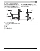
Installation of the roof penetration of a vertical flue
systems
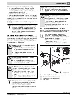
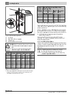
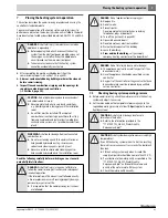
Observe the clearances for the roof exit above the roof (
Fig. 14).
If the flue passes through ceilings at any points, fire plates
(
Fig. 14, [2]) must be installed.
Fig. 14 Vertical flue system with room air for combustion
[1]
Roof penetration
[2]
Fire protection collar
[3]
Fastening the flue pipe
[4]
Flue pipe adaptor (available separately)
[5]
T-piece with siphon to drain condensate
6.5
Connecting the air supply (for direct vent
operations)
The combustion air is supplied to the boiler either through an external
wall connection, through a chimney flue or through a separate pipe in the
chimney flue. For direct vent operation, a suitable air supply system
must be used (made of PVC or CPVC, galvanized steel or other suitable
material).
The flue and air supply system (for design of flue connection,
see
Section 6, page 16) must be designed for a max. pressure of
0.40 inches W.C. for the overall system (flue and air supply system).
Use Tab. 10 or refer to the GB312 Application Manual for detailed
descriptions of maximum permissible vent lengths and dimensioning of
exhaust venting systems.
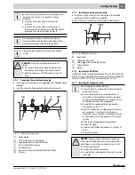
▶ Remove the side panel if not already removed.
▶ Unscrew the cover plate from the rear panel.
▶ Attach the 90° elbow on the air supply system to the air inlet
connection through the rear panel and seal.
▶ Construct the air supply pipe using a standard air pipe system
according to the national requirements.
We recommend installing a safety mesh (bird screen) on the air intake
opening. For details of correct dimensioning, contact the manufacturer
concerned.
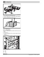
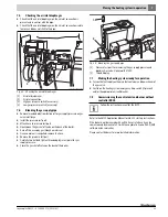
Fig. 15 Connecting the air supply for balanced flue operation
[1]
Bolt
[2]
Air supply restriction plate
All instructions provided by the flue system
manufacturer concerned regarding the installation of the
wall penetration must be followed. Use only those that
are required for the necessary flue pipe diameter. The
use of a T-piece or a 90°-elbow as the external end piece
for the flue pipe is required.
Always make sure that the flue connector is installed
with a downward slope towards the boiler ( ¼ " per foot).
6 720 806 275-01.1T
10 Min
2 Min
3 Min
48"Max
1
2
3
3
4
5
We recommend that the air supply pipe diameter match
the flue pipe diameter.
Boiler size
Required air supply
volumetric flow rate
Recommended air supply
pipe diameter
[ft
N
3
/m]
[inches]
90 - 4
95
5
120 - 4
95
6
160 - 5
130
6
200 - 6
160
8
240 - 7
190
8
280 - 8
220
8
Table 10 Air supply volumetric flow rate/Air supply pipe diameter
To avoid problems when making the gas connection, it is
best to install a 90° elbow for the air intake connection.
Содержание Logano plus GB312
Страница 93: ...Logano plus GB312 6 720 806 273 2013 01 93 Notes ...
Страница 94: ...Logano plus GB312 6 720 806 273 2013 01 94 Notes ...
Страница 95: ...Logano plus GB312 6 720 806 273 2013 01 95 Notes ...
Страница 96: ......


