


Appendix C
SAFE HANDLING OF CMOS INTEGRATED CIRCUIT DEVICES
Many of the integrated circuit devices used in
communications equipment are of the CMOS
(Complementary Metal Oxide
Semiconductor) type. Because of their high
open circuit impedance, CMOS ICs are
vulnerable to damage from static charges.
Care must be taken in handling, shipping, and
servicing them and the assemblies in which
they are used.
Even though protection devices are provided
in CMOS IC inputs, the protection is effective
only against overvoltage in the hundreds of
volts range such as are encountered in an
operating system. In a system, circuit
elements distribute static charges and load the
CMOS circuits, decreasing the chance of
damage. However, CMOS circuits can be
damaged by improper handling of the
modules even in a system.
To avoid damage to circuits, observe the
following handling, shipping, and servicing
precautions.
1. Prior to and while servicing a circuit
module, particularly after moving within
the service area, momentarily touch both
hands to a bare metal earth grounded
surface. This will discharge any static
charge which may have accumulated on
the person doing the servicing.
NOTE
Wearing Conductive Wrist Strap will
minimize static buildup during servicing.
WARNING
When wearing Conductive Wrist Strap, be
careful near sources of high voltage. The
good ground provided by the wrist strap
will also increase the danger of lethal
shock from accidentally touching high
voltage sources.
2. Whenever possible, avoid touching any
electrically conductive parts of the
circuit module with your hands.
3. Normally, circuit modules can be
inserted or removed with power applied
to the unit. However, check the
INSTALLATION and MAINTE-
NANCE sections of the manual as well
as the module schematic diagram to
insure there are no objections to this
practice.
4. When servicing a circuit module, avoid
carpeted areas, dry environments, and
certain types of clothing (silk, nylon,
etc.) because they contribute to static
buildup.
5. All electrically powered test equipment
should be grounded. Apply the ground
lead from the test equipment to the
circuit module before connecting the test
probe. Similarly, disconnect the test
probe prior to removing the ground lead.
6. If a circuit module is removed from the
system, it is desirable to lay it on a
conductive surface (such as a sheet of
aluminum foil) which is connected to
ground through 100k of resistance.
C-1
Содержание R2600 Series
Страница 1: ...GENERAL DYNAMICS R2670 R2625 Series Communications System Analyzer OPERATOR S MANUAL CG 1089 Rev A...
Страница 2: ...CG 1089 Rev A R2670 R2625 Series Communications System Analyzer OPERATOR S MANUAL GENERAL DYNAMICS...
Страница 8: ...3 7 1 3 AC DC Voltmeter 41 3 7 1 4 INT DIST EXT DIST Meter 43 v...
Страница 46: ...This Page Intentionally Left Blank xxxvi...
Страница 66: ...DISPLAY ZONE RF ZONE AUDIO ZONE Figure 3 1 Screen Zone Arrangement 20...
Страница 68: ...Figure 3 2 System Help 22...
Страница 83: ...Figure 3 11 General Sequence Mode Select 37...
Страница 85: ...39 Figure 3 12 RF Display Zone...
Страница 88: ...Figure 3 14 Digital Voltmeter Screens 42...
Страница 102: ...Figure 3 22 Bar Graphs 56...
Страница 107: ...Figure 3 24 Memory Screens 61...
Страница 128: ...This Page Intentionally Left Blank 82...
Страница 202: ...This Page Intentionally Left Blank 156...
Страница 205: ...Figure 11 1 R 2670 with SECURENET Option Housing 159...
Страница 206: ...This Page Intentionally Left Blank 160...
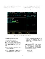
Страница 218: ...Figure 13 8 Test Key Programming Display Figure 13 9 External Key Programming Display 172...
Страница 225: ...Figure 13 12 Duplex Mode Display Zone 179...
Страница 228: ...Figure 13 13 SECURENET Audio Zone Voice Generate Mode Figure 13 13 SECURENET Audio Zone Voice Generate Mode 182 182...
Страница 234: ...VOICE Figure 13 17 CLEAR SCOPE Markers 188...
Страница 236: ...This Page Intentionally Left Blank 190...
Страница 240: ...Figure 14 1 Radio BER Test Mode Audio Zone Figure 14 2 Radio BER Test Mode BER Meter Sample 194...
Страница 249: ...Figure 14 8 SECURENET CLEAR SCOPE Display of Output Modulation 203...
Страница 252: ...This Page Intentionally Left Blank 206...
Страница 255: ...1100 3 RS 232PORT KEYVARIABLE LOADER KVL PORT A S STRO OPTIONHOUSING Figure 15 1 ASTRO Option Housing 209...
Страница 256: ...210 This Page Intentionally Left Blank...
Страница 267: ...Figure 17 7 Encryption Select Display Figure 17 7 Encryption Select Display 221 221...
Страница 286: ...This Page Intentionally Left Blank 240...
Страница 291: ...Figure 18 1 Radio BER Test Mode Audio Zone Figure 18 2 Radio BER Test Mode BER Meter 245...
Страница 293: ...Figure 18 4 Receive BER 247...
Страница 298: ...Figure 18 6 ASTRO CLEAR SCOPE Display of Output Modulation 252...
Страница 304: ...Figure 21 1 PROJ 25 Version Screen Figure 21 2 PROJ 25 Options Screen 258...
Страница 309: ...Figure 21 6 SET UP Display Screen Figure 21 7 Encryption Select Display 263...
Страница 335: ...Figure 22 4 PROJ 25 CONV CLEAR SCOPE Display of Output Modulation 289...
Страница 339: ...Figure 24 1 PROJ 25 Version Screen Figure 24 2 PROJ 25 Options Screen 293...
Страница 354: ...Figure 25 3 Encryption Select Display Figure 25 4 Algorithm Select Display 308...
Страница 369: ...B 6 This Page Intentionally Left Blank...
Страница 379: ...This Page Intentionally Left Blank F 4...
Страница 383: ...This Page Intentionally Left Blank H 2...
Страница 389: ...J 4 This Page Intentionally Left Blank...
Страница 393: ...This Page Intentionally Left Blank K 4...
Страница 399: ...M 2 Table M 3 Registration Call Alert Dispatch Voice Error Messages Error Test Terminated by User Timeout Test Halted...
Страница 401: ...N 2 This Page Intentionally Left Blank...


