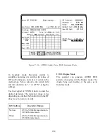


18.7 RADIOS WITH BER TEST
CAPABILITY AND REPEATERS
Radios with BER capability and repeaters can be
tested by the analyzer using the V.52 BER test
pattern. In RF mode, the operation of both the
radio receiver and transmitter can be evaluated.
To set up the analyzer for the BER test, use the
following sequence:
1. Connect the RF IN/OUT port of the
analyzer to the RF port of the radio under
test.
2. Place the cursor in the RF Zone and
configure the analyzer as shown below.
Set the monitor frequency of the analyzer
at the generate frequency of the radio to
be tested, and set the analyzer offset
frequency to correspond to the radio.
3. Set the controls in the Audio Zone as
follows:
ASTRO: 2.55
kHz
Code: BER
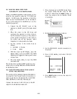
4. With the cursor on RF Display, press the
more
softkey and select BER. The BER
metering will appear in the top left corner
of the screen.
5. Press the
reset
softkey to reset the BER
measurements.
The monitored or generated BIT pattern can be
observed by selecting MODULATION SCOPE
in the Display Zone.
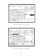
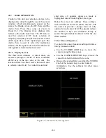
18-8 MONITORING RECEIVED AUDIO
WITH CLEAR SCOPE
This section of the manual contains information
on using the Clear Scope function to monitor an
audio signal that was transmitted by an ASTRO
radio and then recovered by the analyzer.
Connect the analyzer’s RF I/O port to the RF
output of the transmitter under test.
1. Place the analyzer in ASTRO mode. Place
the cursor within the RF Zone in "RF
Control:" field. Press the
MON
softkey to
place the analyzer into its Monitor mode
of operation.
2. Within the RF Zone, set as follows:
RF Control:
Preset: - -
B/W: NB
MONITOR
Freq:
Attenuation:
20 dB
816.5000 MHz
Mon RF In:
RF I/O
Transmitter Carrier
Frequency
3. Set the SQUELCH control on analyzer to
threshold.
4. Press AUD hardkey and select VOICE
FRAME.
Fixed 1kHz:
0.000 V
Code:
VOICE FRAME
External:
0.000 V x
x
5. Press
DISP
hardkey to move the cursor to
the Display Zone.
248
Содержание R2600 Series
Страница 1: ...GENERAL DYNAMICS R2670 R2625 Series Communications System Analyzer OPERATOR S MANUAL CG 1089 Rev A...
Страница 2: ...CG 1089 Rev A R2670 R2625 Series Communications System Analyzer OPERATOR S MANUAL GENERAL DYNAMICS...
Страница 8: ...3 7 1 3 AC DC Voltmeter 41 3 7 1 4 INT DIST EXT DIST Meter 43 v...
Страница 46: ...This Page Intentionally Left Blank xxxvi...
Страница 66: ...DISPLAY ZONE RF ZONE AUDIO ZONE Figure 3 1 Screen Zone Arrangement 20...
Страница 68: ...Figure 3 2 System Help 22...
Страница 83: ...Figure 3 11 General Sequence Mode Select 37...
Страница 85: ...39 Figure 3 12 RF Display Zone...
Страница 88: ...Figure 3 14 Digital Voltmeter Screens 42...
Страница 102: ...Figure 3 22 Bar Graphs 56...
Страница 107: ...Figure 3 24 Memory Screens 61...
Страница 128: ...This Page Intentionally Left Blank 82...
Страница 202: ...This Page Intentionally Left Blank 156...
Страница 205: ...Figure 11 1 R 2670 with SECURENET Option Housing 159...
Страница 206: ...This Page Intentionally Left Blank 160...
Страница 218: ...Figure 13 8 Test Key Programming Display Figure 13 9 External Key Programming Display 172...
Страница 225: ...Figure 13 12 Duplex Mode Display Zone 179...
Страница 228: ...Figure 13 13 SECURENET Audio Zone Voice Generate Mode Figure 13 13 SECURENET Audio Zone Voice Generate Mode 182 182...
Страница 234: ...VOICE Figure 13 17 CLEAR SCOPE Markers 188...
Страница 236: ...This Page Intentionally Left Blank 190...
Страница 240: ...Figure 14 1 Radio BER Test Mode Audio Zone Figure 14 2 Radio BER Test Mode BER Meter Sample 194...
Страница 249: ...Figure 14 8 SECURENET CLEAR SCOPE Display of Output Modulation 203...
Страница 252: ...This Page Intentionally Left Blank 206...
Страница 255: ...1100 3 RS 232PORT KEYVARIABLE LOADER KVL PORT A S STRO OPTIONHOUSING Figure 15 1 ASTRO Option Housing 209...
Страница 256: ...210 This Page Intentionally Left Blank...
Страница 267: ...Figure 17 7 Encryption Select Display Figure 17 7 Encryption Select Display 221 221...
Страница 286: ...This Page Intentionally Left Blank 240...
Страница 291: ...Figure 18 1 Radio BER Test Mode Audio Zone Figure 18 2 Radio BER Test Mode BER Meter 245...
Страница 293: ...Figure 18 4 Receive BER 247...
Страница 298: ...Figure 18 6 ASTRO CLEAR SCOPE Display of Output Modulation 252...
Страница 304: ...Figure 21 1 PROJ 25 Version Screen Figure 21 2 PROJ 25 Options Screen 258...
Страница 309: ...Figure 21 6 SET UP Display Screen Figure 21 7 Encryption Select Display 263...
Страница 335: ...Figure 22 4 PROJ 25 CONV CLEAR SCOPE Display of Output Modulation 289...
Страница 339: ...Figure 24 1 PROJ 25 Version Screen Figure 24 2 PROJ 25 Options Screen 293...
Страница 354: ...Figure 25 3 Encryption Select Display Figure 25 4 Algorithm Select Display 308...
Страница 369: ...B 6 This Page Intentionally Left Blank...
Страница 379: ...This Page Intentionally Left Blank F 4...
Страница 383: ...This Page Intentionally Left Blank H 2...
Страница 389: ...J 4 This Page Intentionally Left Blank...
Страница 393: ...This Page Intentionally Left Blank K 4...
Страница 399: ...M 2 Table M 3 Registration Call Alert Dispatch Voice Error Messages Error Test Terminated by User Timeout Test Halted...
Страница 401: ...N 2 This Page Intentionally Left Blank...


