


7-3.4
System Initiated Phone Interconnect
Test Sequence, Trunk II
Configure the analyzer for trunk mode (paragraph
6-5) and System Initiated Testing (paragraph 6-7).
NOTE
Fleet, Subfleet, and Unit ID information must
be entered before the execution of a System
Initiated test. If a Radio Initiated test is
executed prior to the System Initiated test,
these fields are automatically updated. If
required, refer to paragraph 6-8.1 for in-
formation related to entry and storage of sys-
tem/fleet map configurations.
NOTE
SMARTZONE configures the analyzer to
perform a SMARTZONE affiliation sequence
prior to executing the dispatch test sequence.
If the radio is not capable of SMARTZONE
auto affiliation, the selection should be set to
DISABLED.
1.
Enter the following parameters:
Sig Type:
Trunk II
ID Disp:
HEX or DEC
Call Seq:
PHONE INTERCONNECT
2. Set the System ID to match the radio system
ID and one of the system IDs in the Radio
configuration screen in order to decode radio
ID information.
3. Enter talk group, call type, and unit ID.
NOTE
If an announcement call type is selected, the
operator must also set the talk group to the
announcement talk group monitored by the
radio.
4. Enter the CCTx or Control Channel number.
Enter the VCTx or voice channel number.
NOTE
Splinter channels can only be entered by
frequency. Standard channels can be entered
by frequency or channel number (channel
numbers only map to standard channel
frequencies).
5. Set the monitor attenuation and port selection.
Suggested port selection is RF I/O with 20 dB
attenuation.
6. Set the generator attenuation and port
selection. Suggested port selection is RF I/O
with -50 dB for the level setting.
7. Press the start test softkey.
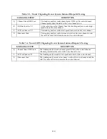
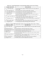
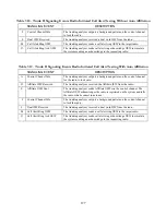
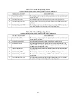
8. The status thermometer displays the major
signaling events that occur during a system
initiated Phone Interconnect test. Refer to
table 7-15 (Trunk II auto affiliation disabled),
or table 7-16 (Trunk II with auto affiliation).
123
Содержание R2600 Series
Страница 1: ...GENERAL DYNAMICS R2670 R2625 Series Communications System Analyzer OPERATOR S MANUAL CG 1089 Rev A...
Страница 2: ...CG 1089 Rev A R2670 R2625 Series Communications System Analyzer OPERATOR S MANUAL GENERAL DYNAMICS...
Страница 8: ...3 7 1 3 AC DC Voltmeter 41 3 7 1 4 INT DIST EXT DIST Meter 43 v...
Страница 46: ...This Page Intentionally Left Blank xxxvi...
Страница 66: ...DISPLAY ZONE RF ZONE AUDIO ZONE Figure 3 1 Screen Zone Arrangement 20...
Страница 68: ...Figure 3 2 System Help 22...
Страница 83: ...Figure 3 11 General Sequence Mode Select 37...
Страница 85: ...39 Figure 3 12 RF Display Zone...
Страница 88: ...Figure 3 14 Digital Voltmeter Screens 42...
Страница 102: ...Figure 3 22 Bar Graphs 56...
Страница 107: ...Figure 3 24 Memory Screens 61...
Страница 128: ...This Page Intentionally Left Blank 82...
Страница 202: ...This Page Intentionally Left Blank 156...
Страница 205: ...Figure 11 1 R 2670 with SECURENET Option Housing 159...
Страница 206: ...This Page Intentionally Left Blank 160...
Страница 218: ...Figure 13 8 Test Key Programming Display Figure 13 9 External Key Programming Display 172...
Страница 225: ...Figure 13 12 Duplex Mode Display Zone 179...
Страница 228: ...Figure 13 13 SECURENET Audio Zone Voice Generate Mode Figure 13 13 SECURENET Audio Zone Voice Generate Mode 182 182...
Страница 234: ...VOICE Figure 13 17 CLEAR SCOPE Markers 188...
Страница 236: ...This Page Intentionally Left Blank 190...
Страница 240: ...Figure 14 1 Radio BER Test Mode Audio Zone Figure 14 2 Radio BER Test Mode BER Meter Sample 194...
Страница 249: ...Figure 14 8 SECURENET CLEAR SCOPE Display of Output Modulation 203...
Страница 252: ...This Page Intentionally Left Blank 206...
Страница 255: ...1100 3 RS 232PORT KEYVARIABLE LOADER KVL PORT A S STRO OPTIONHOUSING Figure 15 1 ASTRO Option Housing 209...
Страница 256: ...210 This Page Intentionally Left Blank...
Страница 267: ...Figure 17 7 Encryption Select Display Figure 17 7 Encryption Select Display 221 221...
Страница 286: ...This Page Intentionally Left Blank 240...
Страница 291: ...Figure 18 1 Radio BER Test Mode Audio Zone Figure 18 2 Radio BER Test Mode BER Meter 245...
Страница 293: ...Figure 18 4 Receive BER 247...
Страница 298: ...Figure 18 6 ASTRO CLEAR SCOPE Display of Output Modulation 252...
Страница 304: ...Figure 21 1 PROJ 25 Version Screen Figure 21 2 PROJ 25 Options Screen 258...
Страница 309: ...Figure 21 6 SET UP Display Screen Figure 21 7 Encryption Select Display 263...
Страница 335: ...Figure 22 4 PROJ 25 CONV CLEAR SCOPE Display of Output Modulation 289...
Страница 339: ...Figure 24 1 PROJ 25 Version Screen Figure 24 2 PROJ 25 Options Screen 293...
Страница 354: ...Figure 25 3 Encryption Select Display Figure 25 4 Algorithm Select Display 308...
Страница 369: ...B 6 This Page Intentionally Left Blank...
Страница 379: ...This Page Intentionally Left Blank F 4...
Страница 383: ...This Page Intentionally Left Blank H 2...
Страница 389: ...J 4 This Page Intentionally Left Blank...
Страница 393: ...This Page Intentionally Left Blank K 4...
Страница 399: ...M 2 Table M 3 Registration Call Alert Dispatch Voice Error Messages Error Test Terminated by User Timeout Test Halted...
Страница 401: ...N 2 This Page Intentionally Left Blank...


