


Section 24
PROJECT 25 TRUNKING OPERATING INSTRUCTIONS
CAUTION
When testing a radio, the analyzer generates a control channel signal. Take care to prevent this
signal from unintentionally capturing other radios in the area. Observe the following precautions:
Do not use an antenna on the analyzer for over-the-air testing.
Use double-shielded cables on the analyzer to carry signals to and from the radio.
Locate the analyzer at least 35 feet from the antenna of a unit that is working in the
same system that the analyzer is testing.
Adjust the squelch to where the LED indicator for squelch just turns off or is
closed. When the signal from the radio is present, the squelch LED will illuminate
indicating that squelch has been detected and there is a signal present.
24-1 INTRODUCTION
The Project 25 Trunking Option is an
enhancement to the R2670 and R2625
Digital Communications System Analyzers.
Refer to sections 1, 2, and 3 under the
General Operation tab in this manual for
general installation information, a
description of the control functions, and
general operational information. The
following sections of this manual contain
information on screen field definitions and
test setup.
Error/Warning Messages
Refer to Appendix M-3 for a listing and
description of error and warning messages
related to the Project 25 trunking test mode.
Messages common to all test modes are
described in paragraph 2-4 under the General
Operation tab of this manual.
24-2 SOFTARE VERSION SCREEN
To view the software version of the R2670
or R2625 Analyzer:
1.
Turn power on and wait for the display
to appear on the screen.
2.
Press the SPF hard key, and move the
cursor to “VERSION”.
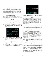
3.
Select the display table softkey. This
will configure the analyzer to generate a
screen that displays the Project 25
software version (figure 24-1).
4. Move the cursor to the Project 25
(PRJ25) position and select the view
options softkey. A screen similar to
figure 24-2 will be displayed. This
screen indicates the analyzer options
installed.
5. Select the return softkey to return to the
power up screen.
292
Содержание R2600 Series
Страница 1: ...GENERAL DYNAMICS R2670 R2625 Series Communications System Analyzer OPERATOR S MANUAL CG 1089 Rev A...
Страница 2: ...CG 1089 Rev A R2670 R2625 Series Communications System Analyzer OPERATOR S MANUAL GENERAL DYNAMICS...
Страница 8: ...3 7 1 3 AC DC Voltmeter 41 3 7 1 4 INT DIST EXT DIST Meter 43 v...
Страница 46: ...This Page Intentionally Left Blank xxxvi...
Страница 66: ...DISPLAY ZONE RF ZONE AUDIO ZONE Figure 3 1 Screen Zone Arrangement 20...
Страница 68: ...Figure 3 2 System Help 22...
Страница 83: ...Figure 3 11 General Sequence Mode Select 37...
Страница 85: ...39 Figure 3 12 RF Display Zone...
Страница 88: ...Figure 3 14 Digital Voltmeter Screens 42...
Страница 102: ...Figure 3 22 Bar Graphs 56...
Страница 107: ...Figure 3 24 Memory Screens 61...
Страница 128: ...This Page Intentionally Left Blank 82...
Страница 202: ...This Page Intentionally Left Blank 156...
Страница 205: ...Figure 11 1 R 2670 with SECURENET Option Housing 159...
Страница 206: ...This Page Intentionally Left Blank 160...
Страница 218: ...Figure 13 8 Test Key Programming Display Figure 13 9 External Key Programming Display 172...
Страница 225: ...Figure 13 12 Duplex Mode Display Zone 179...
Страница 228: ...Figure 13 13 SECURENET Audio Zone Voice Generate Mode Figure 13 13 SECURENET Audio Zone Voice Generate Mode 182 182...
Страница 234: ...VOICE Figure 13 17 CLEAR SCOPE Markers 188...
Страница 236: ...This Page Intentionally Left Blank 190...
Страница 240: ...Figure 14 1 Radio BER Test Mode Audio Zone Figure 14 2 Radio BER Test Mode BER Meter Sample 194...
Страница 249: ...Figure 14 8 SECURENET CLEAR SCOPE Display of Output Modulation 203...
Страница 252: ...This Page Intentionally Left Blank 206...
Страница 255: ...1100 3 RS 232PORT KEYVARIABLE LOADER KVL PORT A S STRO OPTIONHOUSING Figure 15 1 ASTRO Option Housing 209...
Страница 256: ...210 This Page Intentionally Left Blank...
Страница 267: ...Figure 17 7 Encryption Select Display Figure 17 7 Encryption Select Display 221 221...
Страница 286: ...This Page Intentionally Left Blank 240...
Страница 291: ...Figure 18 1 Radio BER Test Mode Audio Zone Figure 18 2 Radio BER Test Mode BER Meter 245...
Страница 293: ...Figure 18 4 Receive BER 247...
Страница 298: ...Figure 18 6 ASTRO CLEAR SCOPE Display of Output Modulation 252...
Страница 304: ...Figure 21 1 PROJ 25 Version Screen Figure 21 2 PROJ 25 Options Screen 258...
Страница 309: ...Figure 21 6 SET UP Display Screen Figure 21 7 Encryption Select Display 263...
Страница 335: ...Figure 22 4 PROJ 25 CONV CLEAR SCOPE Display of Output Modulation 289...
Страница 339: ...Figure 24 1 PROJ 25 Version Screen Figure 24 2 PROJ 25 Options Screen 293...
Страница 354: ...Figure 25 3 Encryption Select Display Figure 25 4 Algorithm Select Display 308...
Страница 369: ...B 6 This Page Intentionally Left Blank...
Страница 379: ...This Page Intentionally Left Blank F 4...
Страница 383: ...This Page Intentionally Left Blank H 2...
Страница 389: ...J 4 This Page Intentionally Left Blank...
Страница 393: ...This Page Intentionally Left Blank K 4...
Страница 399: ...M 2 Table M 3 Registration Call Alert Dispatch Voice Error Messages Error Test Terminated by User Timeout Test Halted...
Страница 401: ...N 2 This Page Intentionally Left Blank...


