


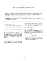


Trunk II or Astro signaling is selected. The
operator has the option of disabling the auto
affiliation sequence, or selecting the
SMARTZONE affiliation sequence. If the
radio is not capable of SMARTZONE auto
affiliation, the selection should be set to
DISABLED.
If auto affiliation is disabled, the analyzer
transmits idle data on the control channel until
the radio initiates the test sequence.
9-6.2
Testing the Auto Affiliation Feature
After setting up the test conditions with the radio
turned "off," press the
start test
softkey to
activate control channel signaling. Turn the radio
"on" when the prompt message appears so it can
lock to the control channel and register.
Successful registration will be indicated by
seeing the squelch indicator LED flash briefly
followed by the presence of decoded radio ID
parameters The call type M1 should be displayed
to indicate that an auto affiliation sequence has
been received. At this time, the radio may be
keyed to proceed with the radio initiated calling
sequence.
The radio will remain registered as long as it
remains powered up and there have been no
changes in basic test configuration. Stopping and
re-starting the test requires re-registration as long
as SMARTZONE is selected at the "Auto Aff:"
field on the screen.
NOTE
If changes to the test setup entries are made
after a test has been started, even though
theses changes appear on the screen, they will
not be entered as part of the test until the test
is ended and restarted. Similarly, if invalid
entries are made for frequency or other
parameters, they may be accepted until a final
validity check is done by the system at the time
the
"start test"
softkey is pressed.
9-6.3 RF
ZONE
Band:
Band selects the frequency channel plan for the
analyzer. For Astro trunked radio, the only
selection is 800 MHz (US). The 800 MHz (US)
band configures the analyzer for the frequency
and channel plan described in table 9-1. This
table shows analyzer transmit frequency
ranges.
CCTx:
CCTx is the control channel transmit frequency
of the analyzer. The control channel frequency
can be changed by moving the cursor into the
CCTx cursor field and changing the value with
the keypad or with the tuning knob. When the
control channel frequency is changed, the
corresponding channel number is also updated.
If the frequency selected is out of range of the
frequency channel plan, the corresponding
channel number will be dashed out.
As a convenience, the control channel can also
be entered by moving the cursor to the
associated channel position on the display and
selecting a channel number with the keypad or
tuning knob. When the channel number is
changed, the corresponding frequency value is
changed. If the channel number selected is out
of range of the frequency channel plan, the
corresponding frequency will be dashed out.
Splinter channels can only be entered by
frequency. Standard channels can be entered by
frequency or channel number (channel
numbers only map to standard channel
frequencies).
VCTx:
VCTx sets the voice channel transmit fre-
quency of the analyzer. The voice channel
frequency can be changed by moving the
cursor into the VCTx cursor field and changing
the value with the keypad or with the tuning
knob. When the voice channel frequency is
141
Содержание R2600 Series
Страница 1: ...GENERAL DYNAMICS R2670 R2625 Series Communications System Analyzer OPERATOR S MANUAL CG 1089 Rev A...
Страница 2: ...CG 1089 Rev A R2670 R2625 Series Communications System Analyzer OPERATOR S MANUAL GENERAL DYNAMICS...
Страница 8: ...3 7 1 3 AC DC Voltmeter 41 3 7 1 4 INT DIST EXT DIST Meter 43 v...
Страница 46: ...This Page Intentionally Left Blank xxxvi...
Страница 66: ...DISPLAY ZONE RF ZONE AUDIO ZONE Figure 3 1 Screen Zone Arrangement 20...
Страница 68: ...Figure 3 2 System Help 22...
Страница 83: ...Figure 3 11 General Sequence Mode Select 37...
Страница 85: ...39 Figure 3 12 RF Display Zone...
Страница 88: ...Figure 3 14 Digital Voltmeter Screens 42...
Страница 102: ...Figure 3 22 Bar Graphs 56...
Страница 107: ...Figure 3 24 Memory Screens 61...
Страница 128: ...This Page Intentionally Left Blank 82...
Страница 202: ...This Page Intentionally Left Blank 156...
Страница 205: ...Figure 11 1 R 2670 with SECURENET Option Housing 159...
Страница 206: ...This Page Intentionally Left Blank 160...
Страница 218: ...Figure 13 8 Test Key Programming Display Figure 13 9 External Key Programming Display 172...
Страница 225: ...Figure 13 12 Duplex Mode Display Zone 179...
Страница 228: ...Figure 13 13 SECURENET Audio Zone Voice Generate Mode Figure 13 13 SECURENET Audio Zone Voice Generate Mode 182 182...
Страница 234: ...VOICE Figure 13 17 CLEAR SCOPE Markers 188...
Страница 236: ...This Page Intentionally Left Blank 190...
Страница 240: ...Figure 14 1 Radio BER Test Mode Audio Zone Figure 14 2 Radio BER Test Mode BER Meter Sample 194...
Страница 249: ...Figure 14 8 SECURENET CLEAR SCOPE Display of Output Modulation 203...
Страница 252: ...This Page Intentionally Left Blank 206...
Страница 255: ...1100 3 RS 232PORT KEYVARIABLE LOADER KVL PORT A S STRO OPTIONHOUSING Figure 15 1 ASTRO Option Housing 209...
Страница 256: ...210 This Page Intentionally Left Blank...
Страница 267: ...Figure 17 7 Encryption Select Display Figure 17 7 Encryption Select Display 221 221...
Страница 286: ...This Page Intentionally Left Blank 240...
Страница 291: ...Figure 18 1 Radio BER Test Mode Audio Zone Figure 18 2 Radio BER Test Mode BER Meter 245...
Страница 293: ...Figure 18 4 Receive BER 247...
Страница 298: ...Figure 18 6 ASTRO CLEAR SCOPE Display of Output Modulation 252...
Страница 304: ...Figure 21 1 PROJ 25 Version Screen Figure 21 2 PROJ 25 Options Screen 258...
Страница 309: ...Figure 21 6 SET UP Display Screen Figure 21 7 Encryption Select Display 263...
Страница 335: ...Figure 22 4 PROJ 25 CONV CLEAR SCOPE Display of Output Modulation 289...
Страница 339: ...Figure 24 1 PROJ 25 Version Screen Figure 24 2 PROJ 25 Options Screen 293...
Страница 354: ...Figure 25 3 Encryption Select Display Figure 25 4 Algorithm Select Display 308...
Страница 369: ...B 6 This Page Intentionally Left Blank...
Страница 379: ...This Page Intentionally Left Blank F 4...
Страница 383: ...This Page Intentionally Left Blank H 2...
Страница 389: ...J 4 This Page Intentionally Left Blank...
Страница 393: ...This Page Intentionally Left Blank K 4...
Страница 399: ...M 2 Table M 3 Registration Call Alert Dispatch Voice Error Messages Error Test Terminated by User Timeout Test Halted...
Страница 401: ...N 2 This Page Intentionally Left Blank...


