


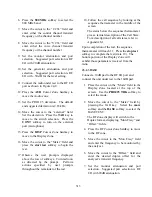


WUID
WGID
RFSS ID
SITE ID
4.
Press the
RF
Cursor Zone hardkey to
move to the RF zone.
5.
Press the
800 MHz
softkey to select the
800 MHz band. Move the cursor to the
“CCTx field and enter either the control
channel transmit frequency or the channel
number.
6. Set the monitor attenuation and port
selection. Suggested port selection is RF
I/O with 20 dB attenuation.
7. Set the generator attenuation and port
selection. Suggested port selection is RF
I/O with –50 dB for the level setting.
8. Press the
AUD
Cursor Zone hardkey to
move the Audio zone.
9. Set the PROJ 25 deviation. The default
and suggested deviation is 2.83 kHz.
10. Connect the radio under test to the RF I/O
port as shown in figure 24-8.
11.
Press the
DISP
Cursor Zone hardkey to
move to the Display zone.
12.
Move the cursor to the “Meter” field and
press the
start test
softkey to begin the
test.
13.
Observe the user prompts displayed
above the row of softkeys. Turn radio on
as directed by the prompt.
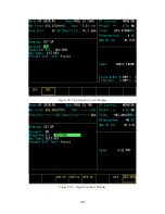
14. Follow the call sequence by looking at the
sequence thermometer in the middle of
the screen.
The status below the sequence thermometer
gives a textual description of the Call State.
For a description of all call states, refer to
Appendix M.
If the call is successful, the thermometer will
reach 8 and the test is completed. The bottom
portion of the Display Zone will exhibit those
parameters received from the radio.
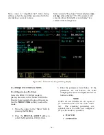
25-4.2 Dispatch Voice
Select the PROJ 25 TRUNK mode by placing
the cursor in the “Mode” field in the Display
Zone located at the top of the screen.
1. Press the
PROJ 25 TRK
softkey to select
the mode.
2. Move the cursor to the “Meter” field by
pressing the
TAB
key.
3. Press the DISPTCH VOICE softkey to
select the Dispatch Voice test.
4. Enter the parameters listed below. If the
parameters are not known, the radio
codeplug must be read using Radio Service
Software (RSS).
NOTE
WACN ID and SYSTEM ID are required
for communication with the radio under
test. The remaining parameters are
optional unless the radio has been
configured for specific modes of operation.
WACN ID
SYSTEM ID
WUID
WGID
RFSS ID
SITE ID
5. Press
the
RF
Cursor Zone hardkey to move
to the RF zone.
312
Содержание R2600 Series
Страница 1: ...GENERAL DYNAMICS R2670 R2625 Series Communications System Analyzer OPERATOR S MANUAL CG 1089 Rev A...
Страница 2: ...CG 1089 Rev A R2670 R2625 Series Communications System Analyzer OPERATOR S MANUAL GENERAL DYNAMICS...
Страница 8: ...3 7 1 3 AC DC Voltmeter 41 3 7 1 4 INT DIST EXT DIST Meter 43 v...
Страница 46: ...This Page Intentionally Left Blank xxxvi...
Страница 66: ...DISPLAY ZONE RF ZONE AUDIO ZONE Figure 3 1 Screen Zone Arrangement 20...
Страница 68: ...Figure 3 2 System Help 22...
Страница 83: ...Figure 3 11 General Sequence Mode Select 37...
Страница 85: ...39 Figure 3 12 RF Display Zone...
Страница 88: ...Figure 3 14 Digital Voltmeter Screens 42...
Страница 102: ...Figure 3 22 Bar Graphs 56...
Страница 107: ...Figure 3 24 Memory Screens 61...
Страница 128: ...This Page Intentionally Left Blank 82...
Страница 202: ...This Page Intentionally Left Blank 156...
Страница 205: ...Figure 11 1 R 2670 with SECURENET Option Housing 159...
Страница 206: ...This Page Intentionally Left Blank 160...
Страница 218: ...Figure 13 8 Test Key Programming Display Figure 13 9 External Key Programming Display 172...
Страница 225: ...Figure 13 12 Duplex Mode Display Zone 179...
Страница 228: ...Figure 13 13 SECURENET Audio Zone Voice Generate Mode Figure 13 13 SECURENET Audio Zone Voice Generate Mode 182 182...
Страница 234: ...VOICE Figure 13 17 CLEAR SCOPE Markers 188...
Страница 236: ...This Page Intentionally Left Blank 190...
Страница 240: ...Figure 14 1 Radio BER Test Mode Audio Zone Figure 14 2 Radio BER Test Mode BER Meter Sample 194...
Страница 249: ...Figure 14 8 SECURENET CLEAR SCOPE Display of Output Modulation 203...
Страница 252: ...This Page Intentionally Left Blank 206...
Страница 255: ...1100 3 RS 232PORT KEYVARIABLE LOADER KVL PORT A S STRO OPTIONHOUSING Figure 15 1 ASTRO Option Housing 209...
Страница 256: ...210 This Page Intentionally Left Blank...
Страница 267: ...Figure 17 7 Encryption Select Display Figure 17 7 Encryption Select Display 221 221...
Страница 286: ...This Page Intentionally Left Blank 240...
Страница 291: ...Figure 18 1 Radio BER Test Mode Audio Zone Figure 18 2 Radio BER Test Mode BER Meter 245...
Страница 293: ...Figure 18 4 Receive BER 247...
Страница 298: ...Figure 18 6 ASTRO CLEAR SCOPE Display of Output Modulation 252...
Страница 304: ...Figure 21 1 PROJ 25 Version Screen Figure 21 2 PROJ 25 Options Screen 258...
Страница 309: ...Figure 21 6 SET UP Display Screen Figure 21 7 Encryption Select Display 263...
Страница 335: ...Figure 22 4 PROJ 25 CONV CLEAR SCOPE Display of Output Modulation 289...
Страница 339: ...Figure 24 1 PROJ 25 Version Screen Figure 24 2 PROJ 25 Options Screen 293...
Страница 354: ...Figure 25 3 Encryption Select Display Figure 25 4 Algorithm Select Display 308...
Страница 369: ...B 6 This Page Intentionally Left Blank...
Страница 379: ...This Page Intentionally Left Blank F 4...
Страница 383: ...This Page Intentionally Left Blank H 2...
Страница 389: ...J 4 This Page Intentionally Left Blank...
Страница 393: ...This Page Intentionally Left Blank K 4...
Страница 399: ...M 2 Table M 3 Registration Call Alert Dispatch Voice Error Messages Error Test Terminated by User Timeout Test Halted...
Страница 401: ...N 2 This Page Intentionally Left Blank...


