


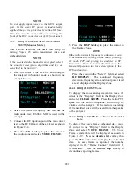


Be sure GENERATE is selected in the RF Zone
in the upper right section of display. Move cursor
to the Audio Zone and place the cursor in the
"Code:" field. Select Voice modulation using the
VOICE FRAME
softkey.
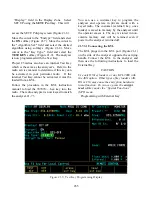
When code VOICE FRAME is selected in the
Audio Zone (Figure 21-14), the analyzer allows
audio inputs to the modulator to be selected from
two sources:
Ex microphone, or
1 kHz tone.
Controls for each modulating input consist of a
switch with values of Off and Continuous. Move
cursor to the appropriate switch field and turn the
modulating input on "~" or off "X" using the
softkeys.
The audio inputs also include a level control for
precisely setting the audio input to the modulator.
Use the keypad or TUNING knob to enter the de-
sired level. The level range varies depending on
whether the bandwidth (in the RF Zone) is set to
narrow or wide.
BW Setting
Audio Level Range
Narrow
0.00 to 9.95 kHz maximum,
in 0.01 kHz increments
Wide
00.0 to 99.5 kHz maximum,
in 0.1 kHz increments
In Generate mode, deviation control is available
in the Audio Zone consisting of a switch with
values of Off and Continuous, and a level control.
Move cursor to the switch field and turn
deviation on "~" or off "X" using the softkeys.
Use the keypad or TUNING knob to enter the de-
sired deviation. The deviation range varies
depending on whether the bandwidth (in the RF
Zone) is set to narrow or wide.
BW Setting
Deviation Range
Narrow
0.00 to 5.00 kHz maximum, in
0.01 kHz increments
Wide
00.0 to 50.0 kHz maximum, in
0.10 kHz increments
The default deviation setting for Project 25 is
2.83 kHz.
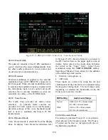
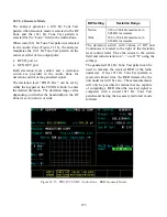
21-9.2.3 Voice Frame Embedded Signaling
(Generate)
When the audio source is selected to Voice
Frame, a
display table
user selection is available
which provides access to the embedded signaling
information contained in voice frames. The
display table presentation is shown in
Figure
21-14. The following information is
encoded by the Project 25:
Embedded Information
Size (bits)
Link Control Field (LCF)
72
Network Access Code (NAC)
12
Low Speed Data(LSD)
96
Status Symbol
2
The LCF information is further decomposed to
allow entry of specific LCF data units. Encoding of
the following LCFs is supported from the user
interface:
Link Control Opcode Identifier
Value
(binary)
Group Voice Chan User
%000000
Unit to Unit Voice Chan User
%000011
Adaptive Power Control
%001111
271
Содержание R2600 Series
Страница 1: ...GENERAL DYNAMICS R2670 R2625 Series Communications System Analyzer OPERATOR S MANUAL CG 1089 Rev A...
Страница 2: ...CG 1089 Rev A R2670 R2625 Series Communications System Analyzer OPERATOR S MANUAL GENERAL DYNAMICS...
Страница 8: ...3 7 1 3 AC DC Voltmeter 41 3 7 1 4 INT DIST EXT DIST Meter 43 v...
Страница 46: ...This Page Intentionally Left Blank xxxvi...
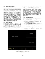
Страница 66: ...DISPLAY ZONE RF ZONE AUDIO ZONE Figure 3 1 Screen Zone Arrangement 20...
Страница 68: ...Figure 3 2 System Help 22...
Страница 83: ...Figure 3 11 General Sequence Mode Select 37...
Страница 85: ...39 Figure 3 12 RF Display Zone...
Страница 88: ...Figure 3 14 Digital Voltmeter Screens 42...
Страница 102: ...Figure 3 22 Bar Graphs 56...
Страница 107: ...Figure 3 24 Memory Screens 61...
Страница 128: ...This Page Intentionally Left Blank 82...
Страница 202: ...This Page Intentionally Left Blank 156...
Страница 205: ...Figure 11 1 R 2670 with SECURENET Option Housing 159...
Страница 206: ...This Page Intentionally Left Blank 160...
Страница 218: ...Figure 13 8 Test Key Programming Display Figure 13 9 External Key Programming Display 172...
Страница 225: ...Figure 13 12 Duplex Mode Display Zone 179...
Страница 228: ...Figure 13 13 SECURENET Audio Zone Voice Generate Mode Figure 13 13 SECURENET Audio Zone Voice Generate Mode 182 182...
Страница 234: ...VOICE Figure 13 17 CLEAR SCOPE Markers 188...
Страница 236: ...This Page Intentionally Left Blank 190...
Страница 240: ...Figure 14 1 Radio BER Test Mode Audio Zone Figure 14 2 Radio BER Test Mode BER Meter Sample 194...
Страница 249: ...Figure 14 8 SECURENET CLEAR SCOPE Display of Output Modulation 203...
Страница 252: ...This Page Intentionally Left Blank 206...
Страница 255: ...1100 3 RS 232PORT KEYVARIABLE LOADER KVL PORT A S STRO OPTIONHOUSING Figure 15 1 ASTRO Option Housing 209...
Страница 256: ...210 This Page Intentionally Left Blank...
Страница 267: ...Figure 17 7 Encryption Select Display Figure 17 7 Encryption Select Display 221 221...
Страница 286: ...This Page Intentionally Left Blank 240...
Страница 291: ...Figure 18 1 Radio BER Test Mode Audio Zone Figure 18 2 Radio BER Test Mode BER Meter 245...
Страница 293: ...Figure 18 4 Receive BER 247...
Страница 298: ...Figure 18 6 ASTRO CLEAR SCOPE Display of Output Modulation 252...
Страница 304: ...Figure 21 1 PROJ 25 Version Screen Figure 21 2 PROJ 25 Options Screen 258...
Страница 309: ...Figure 21 6 SET UP Display Screen Figure 21 7 Encryption Select Display 263...
Страница 335: ...Figure 22 4 PROJ 25 CONV CLEAR SCOPE Display of Output Modulation 289...
Страница 339: ...Figure 24 1 PROJ 25 Version Screen Figure 24 2 PROJ 25 Options Screen 293...
Страница 354: ...Figure 25 3 Encryption Select Display Figure 25 4 Algorithm Select Display 308...
Страница 369: ...B 6 This Page Intentionally Left Blank...
Страница 379: ...This Page Intentionally Left Blank F 4...
Страница 383: ...This Page Intentionally Left Blank H 2...
Страница 389: ...J 4 This Page Intentionally Left Blank...
Страница 393: ...This Page Intentionally Left Blank K 4...
Страница 399: ...M 2 Table M 3 Registration Call Alert Dispatch Voice Error Messages Error Test Terminated by User Timeout Test Halted...
Страница 401: ...N 2 This Page Intentionally Left Blank...


