


81
3. Set the "Format Sel:" to
TONE RMT
. The
base transmitter is activated when the
SYNTH is turned on by pressing the
BURST
key. The level of the fixed 1 kHz tone and
"Synth:" field will vary depending on the
base specifications.
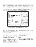
4. With the cursor located within the Display
zone ("Meter:" field), press the
RF DISPLAY
softkey. Monitor the base frequency, power
and deviation.
RF
DISPLAY
AC
VOLLTS
RF
SCAN
RF
Display
Audio Sum:
0.500 V pk
Fixed 1kHz:
Synth:
Format Sel:
TONE RMT
Code:
External:
0.000 V x
0.500 V ~
0.500 V
DTMF:
0.000 V x
- - - - - - - - - - - - - - - -
Meter: RF DISPLAY
Mon Freq: 816.500 MHz
Freq Err: + 47 Hz
Dev: 3.5 kHz
Input Lvl: -70.5 dBm
CONT
x
OFF
BURST
~
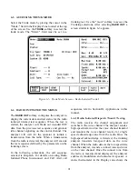
4-5 Analyzer Setup for Printing
The analyzer must use null modem cable to
properly print with any serial printer.
Do not use
a standard serial cable; it will not work!
This is due to the fact that the RS-232 port also is
used as a control port to remotely operate the
analyzer in computer controlled applications.
Different cables are required to activate each
function.
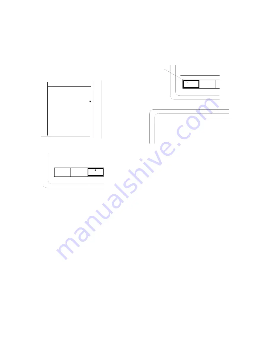
To set up the port for printer operation press the
SPF
key. When in this screen, move the high-
lighted cursor to
RS232 SETUP
and press the
softkey labeled
display table
. This table gives you
the ability to configure the RS-232 output from
the analyzer. Move the cursor to each field and
choose the appropriate softkey entry to match the
printer setup.
Содержание R2600 Series
Страница 1: ...GENERAL DYNAMICS R2670 R2625 Series Communications System Analyzer OPERATOR S MANUAL CG 1089 Rev A...
Страница 2: ...CG 1089 Rev A R2670 R2625 Series Communications System Analyzer OPERATOR S MANUAL GENERAL DYNAMICS...
Страница 8: ...3 7 1 3 AC DC Voltmeter 41 3 7 1 4 INT DIST EXT DIST Meter 43 v...
Страница 46: ...This Page Intentionally Left Blank xxxvi...
Страница 66: ...DISPLAY ZONE RF ZONE AUDIO ZONE Figure 3 1 Screen Zone Arrangement 20...
Страница 68: ...Figure 3 2 System Help 22...
Страница 83: ...Figure 3 11 General Sequence Mode Select 37...
Страница 85: ...39 Figure 3 12 RF Display Zone...
Страница 88: ...Figure 3 14 Digital Voltmeter Screens 42...
Страница 102: ...Figure 3 22 Bar Graphs 56...
Страница 107: ...Figure 3 24 Memory Screens 61...
Страница 128: ...This Page Intentionally Left Blank 82...
Страница 202: ...This Page Intentionally Left Blank 156...
Страница 205: ...Figure 11 1 R 2670 with SECURENET Option Housing 159...
Страница 206: ...This Page Intentionally Left Blank 160...
Страница 218: ...Figure 13 8 Test Key Programming Display Figure 13 9 External Key Programming Display 172...
Страница 225: ...Figure 13 12 Duplex Mode Display Zone 179...
Страница 228: ...Figure 13 13 SECURENET Audio Zone Voice Generate Mode Figure 13 13 SECURENET Audio Zone Voice Generate Mode 182 182...
Страница 234: ...VOICE Figure 13 17 CLEAR SCOPE Markers 188...
Страница 236: ...This Page Intentionally Left Blank 190...
Страница 240: ...Figure 14 1 Radio BER Test Mode Audio Zone Figure 14 2 Radio BER Test Mode BER Meter Sample 194...
Страница 249: ...Figure 14 8 SECURENET CLEAR SCOPE Display of Output Modulation 203...
Страница 252: ...This Page Intentionally Left Blank 206...
Страница 255: ...1100 3 RS 232PORT KEYVARIABLE LOADER KVL PORT A S STRO OPTIONHOUSING Figure 15 1 ASTRO Option Housing 209...
Страница 256: ...210 This Page Intentionally Left Blank...
Страница 267: ...Figure 17 7 Encryption Select Display Figure 17 7 Encryption Select Display 221 221...
Страница 286: ...This Page Intentionally Left Blank 240...
Страница 291: ...Figure 18 1 Radio BER Test Mode Audio Zone Figure 18 2 Radio BER Test Mode BER Meter 245...
Страница 293: ...Figure 18 4 Receive BER 247...
Страница 298: ...Figure 18 6 ASTRO CLEAR SCOPE Display of Output Modulation 252...
Страница 304: ...Figure 21 1 PROJ 25 Version Screen Figure 21 2 PROJ 25 Options Screen 258...
Страница 309: ...Figure 21 6 SET UP Display Screen Figure 21 7 Encryption Select Display 263...
Страница 335: ...Figure 22 4 PROJ 25 CONV CLEAR SCOPE Display of Output Modulation 289...
Страница 339: ...Figure 24 1 PROJ 25 Version Screen Figure 24 2 PROJ 25 Options Screen 293...
Страница 354: ...Figure 25 3 Encryption Select Display Figure 25 4 Algorithm Select Display 308...
Страница 369: ...B 6 This Page Intentionally Left Blank...
Страница 379: ...This Page Intentionally Left Blank F 4...
Страница 383: ...This Page Intentionally Left Blank H 2...
Страница 389: ...J 4 This Page Intentionally Left Blank...
Страница 393: ...This Page Intentionally Left Blank K 4...
Страница 399: ...M 2 Table M 3 Registration Call Alert Dispatch Voice Error Messages Error Test Terminated by User Timeout Test Halted...
Страница 401: ...N 2 This Page Intentionally Left Blank...


