


13-5 TEST
SETUP
13-5.1 Connecting a Radio
Use a 50-ohm BNC cable and an N to BNC
adaptor to connect from the RF I/O port of the
R2670 analyzer to the antenna port of the radio as
shown in figure 13-4.
168
CAUTION
Adjust the squelch to where the led indicator
for squelch just turns off or is closed. When
the signal from the radio is present, the
squelch LED will illuminate indicating that
squelch has been detected and there is a
signal present.
CAUTION
Observe the input power ratings and
warnings of the analyzer to insure that no
damage occurs to the analyzer.
Figure 13-4. Radio to Analyzer Test Setup
DISPLAY
RF
CONTROL
AUDIO
CONTROL
TUNING
MAX INPUT
0dBM
ANT
ON
POWER
DC
BRIGHT
7
8
9
4
5
6
2
3
ALT
0
+/-
1
F1
SPF
PRT
CAL
VOLUME
SQUELCH
CURSOR ZONE
CURSOR POSITION
DISP
RF
AUD
TAB
HELP
MEM
RF IN/OUT
CAUTION
125W MAX
GEN
OUT
CAUTION
DO NOT
INPUT
POWER
VERT/SINAD
DIST/DVM
COUNTER IN
DEMOD
OUT
MOD
OUT
EXT
MOD
IN
MIC
COMMUNICATION SYSTEM ANALYZER
SOFTKEY LABELS
SOFTKEYS
ANTENNA
CONNECTOR
SECURENET RADIO
NOTE
ENSURE THE SQUELCH
HAS BEEN SET PROPERLY
BEFORE ATTACHING THE
RADIO. (REFER TO CAUTION
PREVIOUS PAGE)
GENERAL DYNAMICS
CAUTION
On some radios the antenna connector is not a
center conductor with an outer shield. Ensure the
signal is not shorted to the shield of the BNC cable
by disconnecting the shield at the radio end.
Содержание R2600 Series
Страница 1: ...GENERAL DYNAMICS R2670 R2625 Series Communications System Analyzer OPERATOR S MANUAL CG 1089 Rev A...
Страница 2: ...CG 1089 Rev A R2670 R2625 Series Communications System Analyzer OPERATOR S MANUAL GENERAL DYNAMICS...
Страница 8: ...3 7 1 3 AC DC Voltmeter 41 3 7 1 4 INT DIST EXT DIST Meter 43 v...
Страница 46: ...This Page Intentionally Left Blank xxxvi...
Страница 66: ...DISPLAY ZONE RF ZONE AUDIO ZONE Figure 3 1 Screen Zone Arrangement 20...
Страница 68: ...Figure 3 2 System Help 22...
Страница 83: ...Figure 3 11 General Sequence Mode Select 37...
Страница 85: ...39 Figure 3 12 RF Display Zone...
Страница 88: ...Figure 3 14 Digital Voltmeter Screens 42...
Страница 102: ...Figure 3 22 Bar Graphs 56...
Страница 107: ...Figure 3 24 Memory Screens 61...
Страница 128: ...This Page Intentionally Left Blank 82...
Страница 202: ...This Page Intentionally Left Blank 156...
Страница 205: ...Figure 11 1 R 2670 with SECURENET Option Housing 159...
Страница 206: ...This Page Intentionally Left Blank 160...
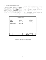
Страница 218: ...Figure 13 8 Test Key Programming Display Figure 13 9 External Key Programming Display 172...
Страница 225: ...Figure 13 12 Duplex Mode Display Zone 179...
Страница 228: ...Figure 13 13 SECURENET Audio Zone Voice Generate Mode Figure 13 13 SECURENET Audio Zone Voice Generate Mode 182 182...
Страница 234: ...VOICE Figure 13 17 CLEAR SCOPE Markers 188...
Страница 236: ...This Page Intentionally Left Blank 190...
Страница 240: ...Figure 14 1 Radio BER Test Mode Audio Zone Figure 14 2 Radio BER Test Mode BER Meter Sample 194...
Страница 249: ...Figure 14 8 SECURENET CLEAR SCOPE Display of Output Modulation 203...
Страница 252: ...This Page Intentionally Left Blank 206...
Страница 255: ...1100 3 RS 232PORT KEYVARIABLE LOADER KVL PORT A S STRO OPTIONHOUSING Figure 15 1 ASTRO Option Housing 209...
Страница 256: ...210 This Page Intentionally Left Blank...
Страница 267: ...Figure 17 7 Encryption Select Display Figure 17 7 Encryption Select Display 221 221...
Страница 286: ...This Page Intentionally Left Blank 240...
Страница 291: ...Figure 18 1 Radio BER Test Mode Audio Zone Figure 18 2 Radio BER Test Mode BER Meter 245...
Страница 293: ...Figure 18 4 Receive BER 247...
Страница 298: ...Figure 18 6 ASTRO CLEAR SCOPE Display of Output Modulation 252...
Страница 304: ...Figure 21 1 PROJ 25 Version Screen Figure 21 2 PROJ 25 Options Screen 258...
Страница 309: ...Figure 21 6 SET UP Display Screen Figure 21 7 Encryption Select Display 263...
Страница 335: ...Figure 22 4 PROJ 25 CONV CLEAR SCOPE Display of Output Modulation 289...
Страница 339: ...Figure 24 1 PROJ 25 Version Screen Figure 24 2 PROJ 25 Options Screen 293...
Страница 354: ...Figure 25 3 Encryption Select Display Figure 25 4 Algorithm Select Display 308...
Страница 369: ...B 6 This Page Intentionally Left Blank...
Страница 379: ...This Page Intentionally Left Blank F 4...
Страница 383: ...This Page Intentionally Left Blank H 2...
Страница 389: ...J 4 This Page Intentionally Left Blank...
Страница 393: ...This Page Intentionally Left Blank K 4...
Страница 399: ...M 2 Table M 3 Registration Call Alert Dispatch Voice Error Messages Error Test Terminated by User Timeout Test Halted...
Страница 401: ...N 2 This Page Intentionally Left Blank...


