


NOTE
Do not apply input power to the GEN output
port. In the event RF power is inadvertently
applied, the port is protected by in-line RF fuse.
This fuse may be accessed by unscrewing the
front of the BNC connector out of the front panel.
22-2 PROJ 25 CONV RADIO TRANSMIT
TESTS (Monitor Mode)
This section describes the basic test setup for
testing Project 25 radio transmitted voice and
embedded data.
NOTE
If the selected radio channel is encrypted, select
the analyzer encryption algorithm and key as
described in Section 21-7.
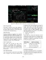
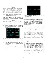
1. Place the cursor in the RF Zone and configure
the analyzer in Monitor mode as shown in the
example below:
2. Select the desired frequency that matches the
radio under test; 806.0625 MHz is used in this
example.
3. Connect the RF input/output of the radio under
test to the RF I/O port of the analyzer as shown
in Figure 21-4.
4. Press the
AUD
hardkey to place the cursor in
the Audio Zone and select
VOICE FRAME
.
5. Press the
DISP
hardkey to place the cursor in
the Display Zone.
NOTE
If the radio transmit frequency is unknown, it can
be determined by turning on the radio, pressing
the radio PTT and placing the analyzer in RF
Scan mode. Refer to Section 21-7.1.2 under the
General Operation tab for a description of the
RF Scan function.
Place the cursor in the “Meter:” Field and select
RF DISPLAY
. The monitored frequency,
deviation, frequency error and input power level
are all displayed in the Display Zone.
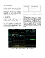
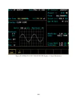
22-2.1 PROJ 25 CONV Voice
To display the voice analog waveform move the
cursor to the “Display:” field in the Display Zone
and select
CLEAR SCOPE
. Press the radio PTT,
speak into the radio microphone, and turn up the
volume on the analyzer. If the radio is operating,
the transmitted voice will be heard from the speaker
of the analyzer.
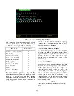
22-2.2 PROJ 25 CONV Voice Frame Embedded
Data
To display the voice frame embedded data, move
the cursor to the “Display:” field in the Display
Zone and select
VOICE FRAME
. The Voice
Frame decode table will be displayed as shown in
Figure 21-19. Press the
decode start
softkey then
press the PTT on the radio to display the embedded
data. As each frame is captured, the number
displayed in the “Frame Counter:” field will be
incremented. Press the
decode stop
softkey to
discontinue capturing frames.
281
Содержание R2600 Series
Страница 1: ...GENERAL DYNAMICS R2670 R2625 Series Communications System Analyzer OPERATOR S MANUAL CG 1089 Rev A...
Страница 2: ...CG 1089 Rev A R2670 R2625 Series Communications System Analyzer OPERATOR S MANUAL GENERAL DYNAMICS...
Страница 8: ...3 7 1 3 AC DC Voltmeter 41 3 7 1 4 INT DIST EXT DIST Meter 43 v...
Страница 46: ...This Page Intentionally Left Blank xxxvi...
Страница 66: ...DISPLAY ZONE RF ZONE AUDIO ZONE Figure 3 1 Screen Zone Arrangement 20...
Страница 68: ...Figure 3 2 System Help 22...
Страница 83: ...Figure 3 11 General Sequence Mode Select 37...
Страница 85: ...39 Figure 3 12 RF Display Zone...
Страница 88: ...Figure 3 14 Digital Voltmeter Screens 42...
Страница 102: ...Figure 3 22 Bar Graphs 56...
Страница 107: ...Figure 3 24 Memory Screens 61...
Страница 128: ...This Page Intentionally Left Blank 82...
Страница 202: ...This Page Intentionally Left Blank 156...
Страница 205: ...Figure 11 1 R 2670 with SECURENET Option Housing 159...
Страница 206: ...This Page Intentionally Left Blank 160...
Страница 218: ...Figure 13 8 Test Key Programming Display Figure 13 9 External Key Programming Display 172...
Страница 225: ...Figure 13 12 Duplex Mode Display Zone 179...
Страница 228: ...Figure 13 13 SECURENET Audio Zone Voice Generate Mode Figure 13 13 SECURENET Audio Zone Voice Generate Mode 182 182...
Страница 234: ...VOICE Figure 13 17 CLEAR SCOPE Markers 188...
Страница 236: ...This Page Intentionally Left Blank 190...
Страница 240: ...Figure 14 1 Radio BER Test Mode Audio Zone Figure 14 2 Radio BER Test Mode BER Meter Sample 194...
Страница 249: ...Figure 14 8 SECURENET CLEAR SCOPE Display of Output Modulation 203...
Страница 252: ...This Page Intentionally Left Blank 206...
Страница 255: ...1100 3 RS 232PORT KEYVARIABLE LOADER KVL PORT A S STRO OPTIONHOUSING Figure 15 1 ASTRO Option Housing 209...
Страница 256: ...210 This Page Intentionally Left Blank...
Страница 267: ...Figure 17 7 Encryption Select Display Figure 17 7 Encryption Select Display 221 221...
Страница 286: ...This Page Intentionally Left Blank 240...
Страница 291: ...Figure 18 1 Radio BER Test Mode Audio Zone Figure 18 2 Radio BER Test Mode BER Meter 245...
Страница 293: ...Figure 18 4 Receive BER 247...
Страница 298: ...Figure 18 6 ASTRO CLEAR SCOPE Display of Output Modulation 252...
Страница 304: ...Figure 21 1 PROJ 25 Version Screen Figure 21 2 PROJ 25 Options Screen 258...
Страница 309: ...Figure 21 6 SET UP Display Screen Figure 21 7 Encryption Select Display 263...
Страница 335: ...Figure 22 4 PROJ 25 CONV CLEAR SCOPE Display of Output Modulation 289...
Страница 339: ...Figure 24 1 PROJ 25 Version Screen Figure 24 2 PROJ 25 Options Screen 293...
Страница 354: ...Figure 25 3 Encryption Select Display Figure 25 4 Algorithm Select Display 308...
Страница 369: ...B 6 This Page Intentionally Left Blank...
Страница 379: ...This Page Intentionally Left Blank F 4...
Страница 383: ...This Page Intentionally Left Blank H 2...
Страница 389: ...J 4 This Page Intentionally Left Blank...
Страница 393: ...This Page Intentionally Left Blank K 4...
Страница 399: ...M 2 Table M 3 Registration Call Alert Dispatch Voice Error Messages Error Test Terminated by User Timeout Test Halted...
Страница 401: ...N 2 This Page Intentionally Left Blank...


