


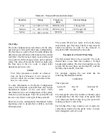


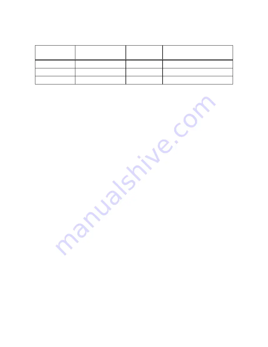
Table 6-5. Transmit Deviation Selections
Selection Range
Frequency
Band
Channel Range
Wide
3.125 kHz
375 Hz
800 MHz (US)
0 through 599
Medium
2.4 kHz
300 Hz
800 MHz (US)
600 through 1022
Narrow
1.2 kHz
300 Hz
900 MHz
900 MHz
Fleet Map
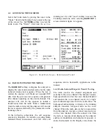
The radio configuration screen allows for the entry
and storage of ten system/fleet map configurations.
The fleet map is a plan of how the radio defines the
data that is passed between the radio and the central
controller. The fleet map is made up of prefixes and
size codes. Each fleet map can have up to eight size
codes. The value of the prefix field is an index into
the fleet map to the size code. A single letter
designates each size code.
NOTE
Fleet Map information should be obtained
from the System Manager. It also should be
resident within the customer maintained data
base for each system.
To enter information in the Radio Configuration
screen, first obtain the system ID from the 10-digit
hexadecimal number on the user label. Then,
determine the size code configuration of the system
from the system manager. Enter the system ID and
the size code letters to the right of the system ID.
Enter the system configuration information before
beginning a test to decode fleet, subfleet, and unit
ID information.
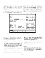
The system ID and size codes of the radio being
tested make up a fleet map. The fleet map must be
entered accurately in order for the analyzer to
decode the ISW transmitted by the radio.
Example of a Trunk I Fleet Map
The first entered item is the system ID. The radio
should have a user label that contains a 10-digit
hexadecimal number. The first four numbers are the
system ID, the next three are the fleet ID, and the
last three the radio ID, (Unit ID).
For example, suppose the user label has the
following hexadecimal number:
0A09400001
This represents:
System ID
Fleet ID
Individual ID
0A09
400
001
The fleet prefix is the first number of the three digit
hexadecimal fleet ID. The value of the prefix field
is an index into the fleet map of a given system for
looking up the size code value.
Each trunked fleet map contains a set of eight size
codes that is indexed by the prefix value. A single
letter designates each size code.
104
Содержание R2600 Series
Страница 1: ...GENERAL DYNAMICS R2670 R2625 Series Communications System Analyzer OPERATOR S MANUAL CG 1089 Rev A...
Страница 2: ...CG 1089 Rev A R2670 R2625 Series Communications System Analyzer OPERATOR S MANUAL GENERAL DYNAMICS...
Страница 8: ...3 7 1 3 AC DC Voltmeter 41 3 7 1 4 INT DIST EXT DIST Meter 43 v...
Страница 46: ...This Page Intentionally Left Blank xxxvi...
Страница 66: ...DISPLAY ZONE RF ZONE AUDIO ZONE Figure 3 1 Screen Zone Arrangement 20...
Страница 68: ...Figure 3 2 System Help 22...
Страница 83: ...Figure 3 11 General Sequence Mode Select 37...
Страница 85: ...39 Figure 3 12 RF Display Zone...
Страница 88: ...Figure 3 14 Digital Voltmeter Screens 42...
Страница 102: ...Figure 3 22 Bar Graphs 56...
Страница 107: ...Figure 3 24 Memory Screens 61...
Страница 128: ...This Page Intentionally Left Blank 82...
Страница 202: ...This Page Intentionally Left Blank 156...
Страница 205: ...Figure 11 1 R 2670 with SECURENET Option Housing 159...
Страница 206: ...This Page Intentionally Left Blank 160...
Страница 218: ...Figure 13 8 Test Key Programming Display Figure 13 9 External Key Programming Display 172...
Страница 225: ...Figure 13 12 Duplex Mode Display Zone 179...
Страница 228: ...Figure 13 13 SECURENET Audio Zone Voice Generate Mode Figure 13 13 SECURENET Audio Zone Voice Generate Mode 182 182...
Страница 234: ...VOICE Figure 13 17 CLEAR SCOPE Markers 188...
Страница 236: ...This Page Intentionally Left Blank 190...
Страница 240: ...Figure 14 1 Radio BER Test Mode Audio Zone Figure 14 2 Radio BER Test Mode BER Meter Sample 194...
Страница 249: ...Figure 14 8 SECURENET CLEAR SCOPE Display of Output Modulation 203...
Страница 252: ...This Page Intentionally Left Blank 206...
Страница 255: ...1100 3 RS 232PORT KEYVARIABLE LOADER KVL PORT A S STRO OPTIONHOUSING Figure 15 1 ASTRO Option Housing 209...
Страница 256: ...210 This Page Intentionally Left Blank...
Страница 267: ...Figure 17 7 Encryption Select Display Figure 17 7 Encryption Select Display 221 221...
Страница 286: ...This Page Intentionally Left Blank 240...
Страница 291: ...Figure 18 1 Radio BER Test Mode Audio Zone Figure 18 2 Radio BER Test Mode BER Meter 245...
Страница 293: ...Figure 18 4 Receive BER 247...
Страница 298: ...Figure 18 6 ASTRO CLEAR SCOPE Display of Output Modulation 252...
Страница 304: ...Figure 21 1 PROJ 25 Version Screen Figure 21 2 PROJ 25 Options Screen 258...
Страница 309: ...Figure 21 6 SET UP Display Screen Figure 21 7 Encryption Select Display 263...
Страница 335: ...Figure 22 4 PROJ 25 CONV CLEAR SCOPE Display of Output Modulation 289...
Страница 339: ...Figure 24 1 PROJ 25 Version Screen Figure 24 2 PROJ 25 Options Screen 293...
Страница 354: ...Figure 25 3 Encryption Select Display Figure 25 4 Algorithm Select Display 308...
Страница 369: ...B 6 This Page Intentionally Left Blank...
Страница 379: ...This Page Intentionally Left Blank F 4...
Страница 383: ...This Page Intentionally Left Blank H 2...
Страница 389: ...J 4 This Page Intentionally Left Blank...
Страница 393: ...This Page Intentionally Left Blank K 4...
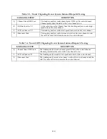
Страница 399: ...M 2 Table M 3 Registration Call Alert Dispatch Voice Error Messages Error Test Terminated by User Timeout Test Halted...
Страница 401: ...N 2 This Page Intentionally Left Blank...


