


21-9.4 Calibration Test Pattern
The Audio Zone provides for selection of a
Calibration Test Pattern when the GENERATE
mode is selected in the RF Zone. This pattern is the
same as the 1011 Hz Tone Test pattern with every
20
th
bit inverted, to yield 172 errors out of 3456
bits. When this pattern is compared with a 1011 Hz
tone test pattern, a 4.977% BER will result. This
pattern conforms to the calibration test pattern
specified in the Digital C4FM/CQPSK Transceiver
Measurement Methods Document TIA/EIA IS-
102.CAAA for the Project 25 system.
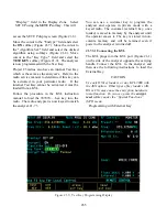
21-9.4.1 Generate Mode
The analyzer generates a Calibration Test Pattern
when Generate mode is selected in the RF Zone
and the Calibration Test Pattern is selected for the
“Code:” field in the Audio Zone.
When code Calibration Test Pattern is selected in
the Audio Zone (Figure 21-16), the analyzer
modulates the Calibration Test Pattern on the
carrier at either of two output ports:
RF I/O port, or
GEN OUT port.
Both deviation level control and a deviation switch
are provided in the Audio Zone for deviation
control of the generated signal.
The deviation level “PRJ25 Dev:” can be set by
either the keypad or the TUNING knob
to enter
the desired deviation. The deviation range varies
depending on whether the bandwidth (in the RF
Zone) is set to narrow or wide.
BW Setting
Deviation Range
Narrow
Wide
0.50 to 5.00 kHz maximum, in
0.05 kHz increments
05.0 to 50.0 kHz maximum, in
0.50 kHz increments
The deviation switch with values of Off and
Continuous is located to the right of the deviation
level control field. Move the cursor to the switch
field and turn deviation on “~” or off “X” using the
softkeys.
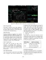
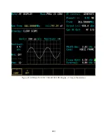
The generated Calibration Test Pattern can be used
to determine if the unit under test receiver is
operating correctly. This is done by computing the
BER for the received calibration test pattern when
compared against a 1011 Hz tone test pattern in the
unit under test. If the Calibration Test Pattern is
received correctly, the measured BER will be
4.977%. These measurements will only be possible
for radios that are capable of computing a BER
when the received signal is compared with a stored
1011 Hz Tone Test pattern and having the
necessary radio test mode software.
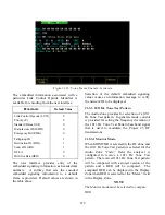
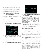
21-9.5 Silence Pattern
The Audio Zone provides for selection of a Silence
Pattern when the GENERATE mode is selected in
the RF Zone. This pattern will produce silence in
the radio under test.
21-9.5.1 Generate Mode
The analyzer generates a Silence Pattern when
Generate mode is selected in the RF Zone and the
Silence Pattern is selected for the “Code:” field in
the Audio Zone.
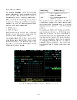
When code Silence Pattern is selected in the Audio
Zone (Figure 21-15), the analyzer modulates to
Silence Pattern on the carrier at either of two output
ports:
RF I/O port, or
GEN OUT port.
Both deviation level control and a deviation switch
are provided in the Audio Zone for deviation
control of the generated signal.
The deviation level “PRJ25 Dev:” can be set by
either the keypad or the TUNING knob to enter the
desired deviation. The deviation range varies
depending on whether the bandwidth (in the RF
Zone) is set to narrow or wide.
BW Setting
Deviation Range
Narrow
Wide
0.50 to 5.00 kHz maximum, in 0.05
kHz increments
05.0 to 50.0 kHz maximum, in 0.50
kHz increments
274
Содержание R2600 Series
Страница 1: ...GENERAL DYNAMICS R2670 R2625 Series Communications System Analyzer OPERATOR S MANUAL CG 1089 Rev A...
Страница 2: ...CG 1089 Rev A R2670 R2625 Series Communications System Analyzer OPERATOR S MANUAL GENERAL DYNAMICS...
Страница 8: ...3 7 1 3 AC DC Voltmeter 41 3 7 1 4 INT DIST EXT DIST Meter 43 v...
Страница 46: ...This Page Intentionally Left Blank xxxvi...
Страница 66: ...DISPLAY ZONE RF ZONE AUDIO ZONE Figure 3 1 Screen Zone Arrangement 20...
Страница 68: ...Figure 3 2 System Help 22...
Страница 83: ...Figure 3 11 General Sequence Mode Select 37...
Страница 85: ...39 Figure 3 12 RF Display Zone...
Страница 88: ...Figure 3 14 Digital Voltmeter Screens 42...
Страница 102: ...Figure 3 22 Bar Graphs 56...
Страница 107: ...Figure 3 24 Memory Screens 61...
Страница 128: ...This Page Intentionally Left Blank 82...
Страница 202: ...This Page Intentionally Left Blank 156...
Страница 205: ...Figure 11 1 R 2670 with SECURENET Option Housing 159...
Страница 206: ...This Page Intentionally Left Blank 160...
Страница 218: ...Figure 13 8 Test Key Programming Display Figure 13 9 External Key Programming Display 172...
Страница 225: ...Figure 13 12 Duplex Mode Display Zone 179...
Страница 228: ...Figure 13 13 SECURENET Audio Zone Voice Generate Mode Figure 13 13 SECURENET Audio Zone Voice Generate Mode 182 182...
Страница 234: ...VOICE Figure 13 17 CLEAR SCOPE Markers 188...
Страница 236: ...This Page Intentionally Left Blank 190...
Страница 240: ...Figure 14 1 Radio BER Test Mode Audio Zone Figure 14 2 Radio BER Test Mode BER Meter Sample 194...
Страница 249: ...Figure 14 8 SECURENET CLEAR SCOPE Display of Output Modulation 203...
Страница 252: ...This Page Intentionally Left Blank 206...
Страница 255: ...1100 3 RS 232PORT KEYVARIABLE LOADER KVL PORT A S STRO OPTIONHOUSING Figure 15 1 ASTRO Option Housing 209...
Страница 256: ...210 This Page Intentionally Left Blank...
Страница 267: ...Figure 17 7 Encryption Select Display Figure 17 7 Encryption Select Display 221 221...
Страница 286: ...This Page Intentionally Left Blank 240...
Страница 291: ...Figure 18 1 Radio BER Test Mode Audio Zone Figure 18 2 Radio BER Test Mode BER Meter 245...
Страница 293: ...Figure 18 4 Receive BER 247...
Страница 298: ...Figure 18 6 ASTRO CLEAR SCOPE Display of Output Modulation 252...
Страница 304: ...Figure 21 1 PROJ 25 Version Screen Figure 21 2 PROJ 25 Options Screen 258...
Страница 309: ...Figure 21 6 SET UP Display Screen Figure 21 7 Encryption Select Display 263...
Страница 335: ...Figure 22 4 PROJ 25 CONV CLEAR SCOPE Display of Output Modulation 289...
Страница 339: ...Figure 24 1 PROJ 25 Version Screen Figure 24 2 PROJ 25 Options Screen 293...
Страница 354: ...Figure 25 3 Encryption Select Display Figure 25 4 Algorithm Select Display 308...
Страница 369: ...B 6 This Page Intentionally Left Blank...
Страница 379: ...This Page Intentionally Left Blank F 4...
Страница 383: ...This Page Intentionally Left Blank H 2...
Страница 389: ...J 4 This Page Intentionally Left Blank...
Страница 393: ...This Page Intentionally Left Blank K 4...
Страница 399: ...M 2 Table M 3 Registration Call Alert Dispatch Voice Error Messages Error Test Terminated by User Timeout Test Halted...
Страница 401: ...N 2 This Page Intentionally Left Blank...


