sary to refill the cooling system after a short peri-
od of use, as the air will naturally bleed out of the
system.
CHECK EXHAUST SYSTEM
The exhaust provides heating for the Screed surface
contacting the asphalt mat, when diverted to that area.
Make sure there are no leaks or loose connections.
NOTE:
Perform all other service requirements
up to this point as well as the following.
REPLACE HYDRAULIC FLUID
& STRAINER
Clean all dirt and debris off the area where the
hydraulic system suction (large) hose connects to the
inside wall of the Hydraulic Reservoir.
1. Remove the Drain Plug from the bottom of the
Reservoir. Allow all the oil to drain out.
NOTE:
DO NOT discharge onto ground. Catch
and dispose of per local waste disposal regula-
tions.
2. Disconnect the suction hose and remove to Sump
Strainer from inside the Reservoir. Inspect the
Strainer. If it shows any damage, holes, etc. it
should be replaced. Otherwise wash it clean with
an industrial solvent, dry with a rag and coat with
fresh hydraulic oil. Install the Strainer and recon-
nect the hose.
3. Flush out the bottom of the Reservoir with clean
hydraulic oil and wipe out any debris. Re-install
the Strainer, Drain Plug and reconnect the suction
hose.
4. Fill the Reservoir with fresh hydraulic oil. Follow
specifications found in the Lubrication capater of
this manual.
NOTE:
Hydraulic fluid and Filters should be
replaced anytime contamination is present before
the normally scheduled change.
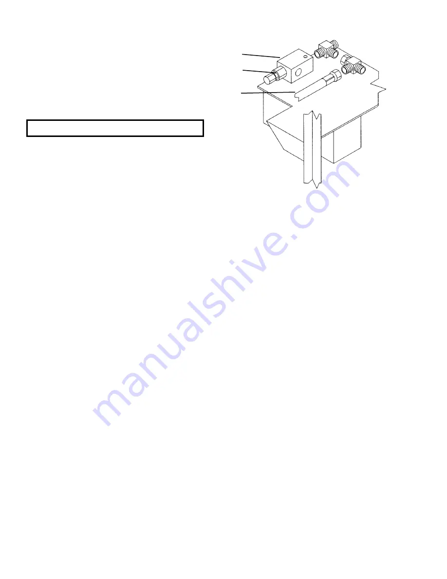
TRACK HYDRAULIC PRESSURE
ADJUSTMENT (Fig. 17)
Hydraulic pressure on the Front Idler Hub is achieved
from an adjustable Relief Valve located on a backwall
plate just behind the Screed Lift Cylinder. The pressure
must be maintained between 250 PSI minimum and
300 PSI maximum.
If the Tracks are not adjusting corrrectly, it may be nec-
essary to check this pressure. Install a 0-500 PSI Gauge
into the test port hose from the Relief Tee fitting. This
Relief Valve connects hydraulically on the return side
of the 7-Stack Main Valve. Increase the pressure as fol-
lows:
1. Remove the Cap on the of the Relief Valve and
losen the Jam Nut.
2. Increase the pressure by turning the Allen Screw
clockwise.
3. The Engine must be running and at minimum 1/2
throttle.
4. When pressure is corrected, tighten Jam Nut,
replace Cap and remove Gauge from test port
hose.
Fig. 17
1
. Relief Valve
2.
Jam Nut
3.
Test Port Hose From Tee Fitting
Service Every 2000 Hours
1
2
3
907389/AP297
52
Printed In U.S.A.
Discount-Equipment.com
Содержание PowerBox 1639
Страница 13: ...SAFETY Continued Printed In U S A 13 907389 AP297 D i s c o u n t E q u i p m e n t c o m...
Страница 14: ...SAFETY Continued 907389 AP297 14 Printed In U S A D i s c o u n t E q u i p m e n t c o m...
Страница 54: ...1639 Electrical Schematic 907389 AP297 56 Printed In U S A D i s c o u n t E q u i p m e n t c o m...
Страница 55: ...1649 Electrical Schematic Printed In U S A 57 907389 AP297 D i s c o u n t E q u i p m e n t c o m...
Страница 65: ...INTERNATIONAL SYMBOLS D i s c o u n t E q u i p m e n t c o m...


