260
(4) Check the installation status of the airbag assembly.
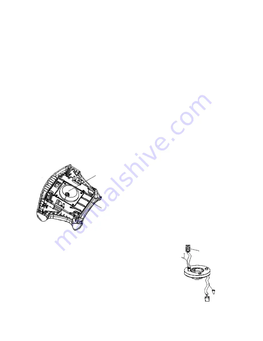
4. Driver airbag assembly (see the figure below)
5. Clock spring (see the figure on the right)
(1) Check the union joint and protecting tube for damage and the
terminal for distortion.
(2) Check the case for distortion.
6. Steering wheel, steering column and steering lower shaft component.
(1) Check the installation status of driver airbag assembly.
(2) Check the steering wheel for any abnormal noise and see if the
clearance is normal.
7. Check the wire harness joint (instrument panel wire harness).
8. Check and see if the wire harness is securely installed, if the joint is damaged and if the terminal is
distorted.
NOTICE
1. Work must be started 60s after the negative (-) terminal cable is disconnected from battery. The
disconnected negative (-) terminal cable shall be protected with insulating tape for insulation.
2. Airbag assembly and clock spring shall not be removed or repaired. They shall be replaced if there is
any trouble.
3. Pay enough attention to airbag assembly and clock spring when using, avoiding dropping them onto the
ground or into water or oil. In addition, if there is any pitting, crack or distortion on them, replace with
new ones.
4. When an airbag is deployed, the deployed surface should face up. It should be kept on a flat surface
without any other items on it.
5. Don’t keep an airbag in a place where the temperature is higher than 93°C.
6. When an airbag is deployed, it shall be replaced with a new one; simultaneously, check the clock spring,
and replace it with a new one if found abnormal.
7. When deal with the deployed airbag, gloves and protective glasses are to be used.
8. When scrapping the undeployed airbag, it shall be discarded after being deployed.
Generator
Bracket
Driver Side
Clock Spring
To Horn
To Driver Module
Содержание CK MR479Q 2007
Страница 1: ......
Страница 52: ...45 Section 4 Fuel Pump Replacement Figure 102 ...
Страница 57: ...50 Chapter 5 Exhaust System MR7131A MR7151A MR7161A Component1 Figure 116 ...
Страница 63: ...56 Chapter 7 Clutch MR7131A MR7151A MR7161A Component 1 Hydraulic Manipulation Figure 131 ...
Страница 66: ...59 Chapter 8 Maunal Transaxle Assembly MR7131A MR7151A MR7161A Component 1 Figure 139 ...
Страница 143: ...136 Section 4 Power Steering Gear Retaining Device Components Front Cowl Panel Assembly Cotter Pin Cotter Pin ...
Страница 208: ...201 High Mounted Stop Lamp LH Rear Combined Lamp Rear Trunk Lamp Switch License Plate Lamp RH rear Combined Lamp ...
Страница 246: ...239 Tweeter Antenna Cable Antenna Assembly Front Speaker Assembly Rear Speaker Assembly ...
Страница 300: ...293 8 Remove the whole HECU from the bracket ABS HECU Assembly ABS HECU Brake Pipe Removal Schematic ...
Страница 387: ...380 5 24 1 2 3 4 Figure 5 24 COWL 1 Cowl 2 Heat Insulating Protecting Board 3 Front Cross Member 4 Heat Insulating Pad ...


