6. Control Functions and Parameter Settings
6-48
B43-0~4
PID control
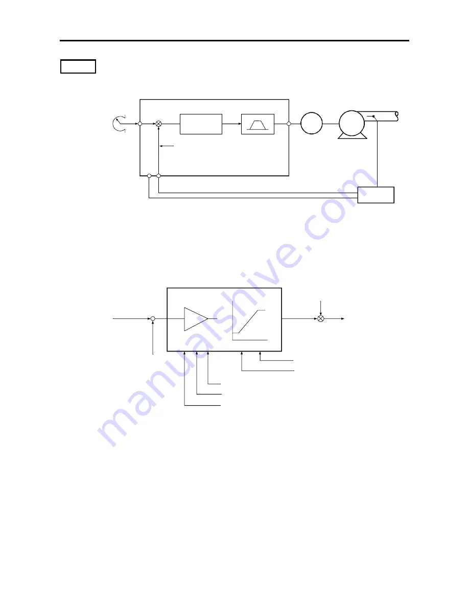
The analog input (FSV, FSI, AUX) can be configured as a feedback loop as shown below.
The below is an example. It is possible to use any analog input either as setting or feedback.
PID
M
0-10V
AU X
C O M
C 12-4(ga in)
VAT2000
press ure sen so r
C onvert er
FS V o r FS I
0-10V
4-20m A
+
-
Pum p
Example of PID control configuration
(Note 1)
PID control functions only in the remote mode (LCL LED OFF)
(Note 2)
PID control functions in respect to the sequence command FRUN or RRUN, but
does not operate with other sequence commands like Jog for example
The PID operation block is shown below,
D ifere ntia l tim e co nsta nt (B 4 3-2 )
U p pe r lim ite r (B 43 -3)
L ow e r lim ite r (B 43 -3)
FS V o r FS I
A U X or FS I
M ax freq ue ncy (B 0 0-4 )
M ax. sp ee d (B 01 -4 )
0 to 10 0%
L im it
Fre q ue ncy
o r spe ed con tro l
In te gra l tim e co nsta nt (B 4 3-1)
P ro po rtion al g ain (B 43 -0)
(1) Is possible to enable or disable the PID control during operation by switching ON or
OFF the sequence input function PIDEN. This can be controlled by one of the
programmable digital inputs.
(2) Refer to fig 5-9 and select the PID’s setting input.
(3) Set the analog input to be used as feedback with C07-5. Set the range of the selected
analog input with block parameters C12.
(4) If the feedback signals must be 4-20mA type, use FSI as feedback. However would be
possible to use AUX for 4-20mA signals, setting C12-2=2 to fix AUX input in range of 1-
5V, and then connect a external resistor of 250 Ohms, 1%, 1/2W, between AUX and
COM terminals.


