


MAINTENANCE: Checkout Procedure
Revision D
APEX Telemetry Transmitter
3-17
401566-166
Hardware Time-Out and
System Leak Check
1.
Press and hold the
button and turn the Accutracker on.
NOTE
Make sure no external pressure is applied to the
Accutracker when you turn it on.
2.
Apply 200mmHg pressure to the Accutracker pressure circuit and
start a timer to clock the Hardware Time-Out circuit.
3.
The Hardware Time-Out should occur in three minutes (+/–45
seconds). Valve #1 should open and dump pressure once the time-out
is finished. As you monitor the Time-Out, monitor the pressure (in
mmHg) displayed on the Accutracker LCD. The Accutracker should
leak no more than 2mmHg per minute.
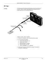
Communication Test
This procedure verifies that the telemetry system transmits and receives
the data correctly from the Accutracker.
1.
Attach the Accutracker to the APEX Telemetry system.
NOTE
You must have ECG leads with a shorting cable or
simulator attached to the APEX Telemetry system for
this test to work.
CAUTION
Refer to the Operator’s Manual for proper operation
guidelines and cuff/microphone placement.
2.
Place blood pressure cuff on the arm.
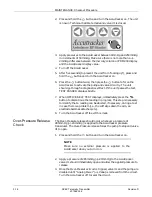
3.
Turn the Accutracker on and press the
button.
4.
When the display appears on the system screen, verify that the
Accutracker display numbers match the display numbers.
5.
Turn Accutracker off.
Содержание Marquette 418793-001
Страница 1: ...APEX Telemetry Transmitter Service Manual 401566 166 Revision D ...
Страница 8: ...CONTENTS vi APEX Telemetry Transmitter Revision D 401566 166 ...
Страница 100: ...TRANSMITTER PCB Schematic Diagram PN SD801278 001A 7 30 APEX Telemetry Transmitter Revision D 401566 166 Sheet 7 of 13 ...
Страница 101: ...TRANSMITTER PCB Schematic Diagram PN SD801278 001A Revision D APEX Telemetry Transmitter 7 31 401566 166 Sheet 8 of 13 ...
Страница 102: ...TRANSMITTER PCB Schematic Diagram PN SD801278 001A 7 32 APEX Telemetry Transmitter Revision D 401566 166 Sheet 9 of 13 ...
Страница 103: ...TRANSMITTER PCB Schematic Diagram PN SD801278 001A Revision D APEX Telemetry Transmitter 7 33 401566 166 Sheet 10 of 13 ...
Страница 104: ...TRANSMITTER PCB Schematic Diagram PN SD801278 001A 7 34 APEX Telemetry Transmitter Revision D 401566 166 Sheet 11 of 13 ...
Страница 105: ...TRANSMITTER PCB Schematic Diagram PN SD801278 001A Revision D APEX Telemetry Transmitter 7 35 401566 166 Sheet 12 of 13 ...
Страница 106: ...TRANSMITTER PCB Schematic Diagram PN SD801278 001A 7 36 APEX Telemetry Transmitter Revision D 401566 166 Sheet 13 of 13 ...
Страница 122: ...OXIMETER ASSEMBLY Parts Location Diagram 421191 001A 8 14 APEX Telemetry Transmitter Revision D 401566 166 Sheet 2 of 3 ...
Страница 123: ...OXIMETER ASSEMBLY Parts Location Diagram 421191 001A Revision D APEX Telemetry Transmitter 8 15 401566 166 Sheet 3 of 3 ...


