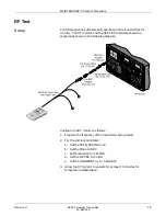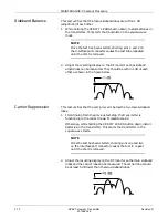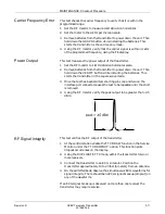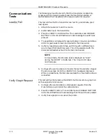
MAINTENANCE: Checkout Procedure
3-16
APEX Telemetry Transmitter
Revision D
401566-166
2.
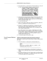
Press and hold the
button and turn the Accutracker on. The unit
is now in Technical Calibrate mode and valve #1 is closed.
3.
Apply pressures to the Accutracker between 0mmHg and 250mmHg
in increments of 50mmHg. Make sure there is no more than a +/–
2mmHg difference between the mercury column or PDM200 display
and the Accutracker display value.
4.
Turn off the Accutracker.
5.
After five seconds (to prevent the unit from “locking up”), press and
hold the
button and turn the Accutracker on.
6.
Press the
button twice; then press the
button to force the
Accutracker to activate the pump and valve circuitry. The unit
should go through a diagnostic self-test. If the unit passes the test,
TEST PASSED displays briefly.
7.
When OFFICE SELF TEST displays, immediately press the
button to discontinue the reading in progress. This step is necessary
to identify that a reading can be aborted, if necessary, during a test
in case there is a problem (i.e., the cuff slips down the arm, an
electrode becomes detached, etc.).
8.
Turn the Accutracker off to exit this mode.
Over-Pressure Release
Check
The Over-Pressure release should occur whenever a pressure of
285mmHg (+/–20mmHg) is applied to the Accutracker pressure
transducer. The Over-Pressure release forces the pump to stop and valve
#1 to open.
1.
Press and hold the
button and turn the Accutracker on.
NOTE
Make sure no external pressure is applied to the
Accutracker when you turn it on.
2.
Apply a pressure of 285mmHg (+/–20mmHg) to the Accutracker.
valve #1 should immediately open and allow the applied pressure to
release.
3.
Once the Over-Pressure circuit is tripped, valve #1 and the pump are
disabled until “Analog Power” (+/–Vana) is removed from the circuit.
Turn the Accutracker off to reset the circuit.
+
Содержание Marquette 418793-001
Страница 1: ...APEX Telemetry Transmitter Service Manual 401566 166 Revision D ...
Страница 8: ...CONTENTS vi APEX Telemetry Transmitter Revision D 401566 166 ...
Страница 100: ...TRANSMITTER PCB Schematic Diagram PN SD801278 001A 7 30 APEX Telemetry Transmitter Revision D 401566 166 Sheet 7 of 13 ...
Страница 101: ...TRANSMITTER PCB Schematic Diagram PN SD801278 001A Revision D APEX Telemetry Transmitter 7 31 401566 166 Sheet 8 of 13 ...
Страница 102: ...TRANSMITTER PCB Schematic Diagram PN SD801278 001A 7 32 APEX Telemetry Transmitter Revision D 401566 166 Sheet 9 of 13 ...
Страница 103: ...TRANSMITTER PCB Schematic Diagram PN SD801278 001A Revision D APEX Telemetry Transmitter 7 33 401566 166 Sheet 10 of 13 ...
Страница 104: ...TRANSMITTER PCB Schematic Diagram PN SD801278 001A 7 34 APEX Telemetry Transmitter Revision D 401566 166 Sheet 11 of 13 ...
Страница 105: ...TRANSMITTER PCB Schematic Diagram PN SD801278 001A Revision D APEX Telemetry Transmitter 7 35 401566 166 Sheet 12 of 13 ...
Страница 106: ...TRANSMITTER PCB Schematic Diagram PN SD801278 001A 7 36 APEX Telemetry Transmitter Revision D 401566 166 Sheet 13 of 13 ...
Страница 122: ...OXIMETER ASSEMBLY Parts Location Diagram 421191 001A 8 14 APEX Telemetry Transmitter Revision D 401566 166 Sheet 2 of 3 ...
Страница 123: ...OXIMETER ASSEMBLY Parts Location Diagram 421191 001A Revision D APEX Telemetry Transmitter 8 15 401566 166 Sheet 3 of 3 ...


