


UPPER LEVEL ASSEMBLY: Theory of Operation
Revision D
APEX Telemetry Transmitter
6-7
401566-166
Power Supply Circuit
A diode (CR102) is connected across the batteries to protect the
transmitter in the event of battery reversal (sheet 7). A zener diode
across each supply voltage (CR6, CR7, CR8) protects against overvoltage
due to static or defibrillation. A PTC (positive temperature coefficient)
resistor RP1 is included in series with the batteries to keep current flow
to a minimum during the event of reversed batteries.
Step-up converters U104 and U105 produce 6.0 and 3.3 volt
power supplies from the battery power. These converters produce the
desired voltage levels as the battery output voltage varies through the
battery’s life. A filter circuit on the output of each converter smooths the
power supply signals.
Modulator Drive and Filter
Circuit
The modulator drive circuit (U111 on sheet 9) provides the mixer of the
frequency modulator with adequate drive and provides an 8-pole linear
phase filter to reduce sideband harmonics and assures a constant phase
delay in the 6.12kHz bandpass.
RF Section
The RF section of the transmitter generates a carrier frequency which is
phase modulated by the digital data. The circuitry consists of a phase
locked loop frequency synthesizer section, a frequency doubler section, a
frequency modulator section, an output amplifier section, and the
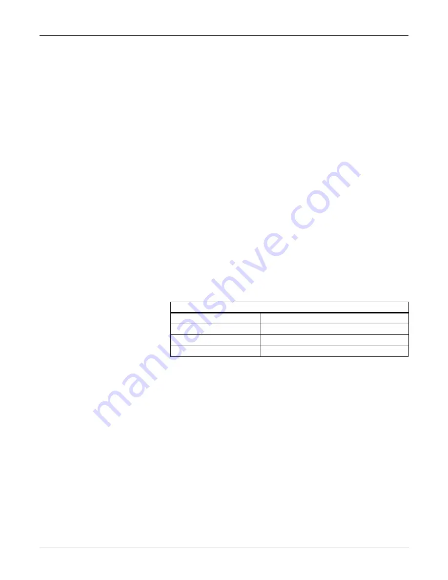
antenna. The carrier frequency can be programmed to any frequency
within a specific range as shown in the table below with a frequency
synthesizer. The transmitter is built with one of the four distinct RF
sections at the factory.
Programmable Frequencies for the RF Section
VHF U.S.
174.05 to 215.95 MHz
VHF International
216.00 to 242.00 MHz
VHF United Kingdom
173.30, 173.75, 173.85, 173.95 MHz
UHF International
430.00 to 474.00 MHz
Содержание Marquette 418793-001
Страница 1: ...APEX Telemetry Transmitter Service Manual 401566 166 Revision D ...
Страница 8: ...CONTENTS vi APEX Telemetry Transmitter Revision D 401566 166 ...
Страница 100: ...TRANSMITTER PCB Schematic Diagram PN SD801278 001A 7 30 APEX Telemetry Transmitter Revision D 401566 166 Sheet 7 of 13 ...
Страница 101: ...TRANSMITTER PCB Schematic Diagram PN SD801278 001A Revision D APEX Telemetry Transmitter 7 31 401566 166 Sheet 8 of 13 ...
Страница 102: ...TRANSMITTER PCB Schematic Diagram PN SD801278 001A 7 32 APEX Telemetry Transmitter Revision D 401566 166 Sheet 9 of 13 ...
Страница 103: ...TRANSMITTER PCB Schematic Diagram PN SD801278 001A Revision D APEX Telemetry Transmitter 7 33 401566 166 Sheet 10 of 13 ...
Страница 104: ...TRANSMITTER PCB Schematic Diagram PN SD801278 001A 7 34 APEX Telemetry Transmitter Revision D 401566 166 Sheet 11 of 13 ...
Страница 105: ...TRANSMITTER PCB Schematic Diagram PN SD801278 001A Revision D APEX Telemetry Transmitter 7 35 401566 166 Sheet 12 of 13 ...
Страница 106: ...TRANSMITTER PCB Schematic Diagram PN SD801278 001A 7 36 APEX Telemetry Transmitter Revision D 401566 166 Sheet 13 of 13 ...
Страница 122: ...OXIMETER ASSEMBLY Parts Location Diagram 421191 001A 8 14 APEX Telemetry Transmitter Revision D 401566 166 Sheet 2 of 3 ...
Страница 123: ...OXIMETER ASSEMBLY Parts Location Diagram 421191 001A Revision D APEX Telemetry Transmitter 8 15 401566 166 Sheet 3 of 3 ...


