


MAINTENANCE: Checkout Procedure
3-14
APEX Telemetry Transmitter
Revision D
401566-166
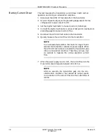
Change Battery Message
This test verifies that the CHANGE BATTERY message displays at the
central station when a battery nears depletion.
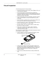
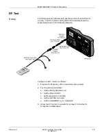
1.
Connect the transmitter to the APEX RF test cable and a low-voltage
power supply as shown previously in this procedure.
2.
Connect an ECG simulator to the transmitter.
3.
Verify that ECG signals from the transmitter are being displayed on
the central station.
4.
Lower the power supply voltage to 1.84 to 1.86 volts.
5.
Verify that a CHANGE BATTERY message is displayed on the
central station.
Completion
If the transmitter fails any of the above tests, return it to GE Marquette
for repair.
Oximeter
Operational Tests
Do the following to ensure the functionality of the APEX oximeter.
Equipment required: Marquette SpO
2
simulator (p/n 408610-001)
Nonin simulator cable adapter (p/n 420970-001).
1.
Record the unit’s serial number.
2.
Connect the oximeter to the Apex S transmitter.
3.
Admit the transmitter to a V6 CDT-LAN system. Make sure that the
SpO
2
parameter box comes up on the Central display and contains
information matching the oximeter’s display. If the unit fails,
discontinue the test. Return or repair the unit after double-checking
the test setup.
4.
Place the oximeter in continuous display mode be pressing and
holding the “Display On/Off switch for 2 seconds.
5.
Connect the Unit Under Test (UUT) to the GE Marquette pulse
oximeter simulator with the selector switch set to “Nellcor.” Check
the heart rate accuracy. Specification for 18 – 300 BPM is +/– 3% or
+/–1, whichever is greater. Adjust the RATE (BPM) switch to vary
the heart rate. Set to 70 BPM. Accuracy at 70 BPM is +/–2. Repeat
for 100 BPM (+/–3) and 160 BPM (+/–5).
6.
Set the simulator to 68.4% (use the white Nellcor numbers).
Accuracy at 68% is +/–3. Repeat for 90.6% (+/–3), 96% (+/–3), and
99% (+/–3).
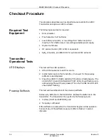
Po
wer
Displa
y
On/Off
Pulse Rate
SpO %
2
Perfusion
o
x
i m
e
t e
r
Содержание Marquette 418793-001
Страница 1: ...APEX Telemetry Transmitter Service Manual 401566 166 Revision D ...
Страница 8: ...CONTENTS vi APEX Telemetry Transmitter Revision D 401566 166 ...
Страница 100: ...TRANSMITTER PCB Schematic Diagram PN SD801278 001A 7 30 APEX Telemetry Transmitter Revision D 401566 166 Sheet 7 of 13 ...
Страница 101: ...TRANSMITTER PCB Schematic Diagram PN SD801278 001A Revision D APEX Telemetry Transmitter 7 31 401566 166 Sheet 8 of 13 ...
Страница 102: ...TRANSMITTER PCB Schematic Diagram PN SD801278 001A 7 32 APEX Telemetry Transmitter Revision D 401566 166 Sheet 9 of 13 ...
Страница 103: ...TRANSMITTER PCB Schematic Diagram PN SD801278 001A Revision D APEX Telemetry Transmitter 7 33 401566 166 Sheet 10 of 13 ...
Страница 104: ...TRANSMITTER PCB Schematic Diagram PN SD801278 001A 7 34 APEX Telemetry Transmitter Revision D 401566 166 Sheet 11 of 13 ...
Страница 105: ...TRANSMITTER PCB Schematic Diagram PN SD801278 001A Revision D APEX Telemetry Transmitter 7 35 401566 166 Sheet 12 of 13 ...
Страница 106: ...TRANSMITTER PCB Schematic Diagram PN SD801278 001A 7 36 APEX Telemetry Transmitter Revision D 401566 166 Sheet 13 of 13 ...
Страница 122: ...OXIMETER ASSEMBLY Parts Location Diagram 421191 001A 8 14 APEX Telemetry Transmitter Revision D 401566 166 Sheet 2 of 3 ...
Страница 123: ...OXIMETER ASSEMBLY Parts Location Diagram 421191 001A Revision D APEX Telemetry Transmitter 8 15 401566 166 Sheet 3 of 3 ...


