


MAINTENANCE: Checkout Procedure
Revision D
APEX Telemetry Transmitter
3-15
401566-166
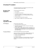
7.
Check the perfusion indication. Change the selector switch to
“Ohmeda” and verify that the perfusion LED changes to yellow.
Completion
Remove the cable from the oximeter. The _ indicator should light in front
of the SpO
2
value on the oximeter and a “CHECK PROBE” message
should appear on the Centralscope.
Accutracker DX NIBP
Operational Tests
NOTE
If the Accutracker fails any test, return the unit to GE
Marquette Medical Systems Service and Supplies. See
“How to Reach Us” in Chapter 1.
Accutracker Display
The following displays on the Accutracker when you turn it on (press and
hold the
button while turning the switch on). This display includes
hardware and software version, the Gain Setting for the mic, and the
pressure setting (mmHg).
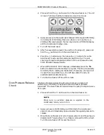
Pressure Calibration
Check
Do the following to ensure the functionality of the Accutracker DX
Noninvasive Blood Pressure monitor.
1.
Connect the PDM200 or Mercury manometer to the patient cable/cuff
connection.
NOTE
Make sure no external pressure is applied to the
Accutracker when you turn it on.
Software Version
Hardware Version
Mercury Pressure in mm
Gain Setting
Содержание Marquette 418793-001
Страница 1: ...APEX Telemetry Transmitter Service Manual 401566 166 Revision D ...
Страница 8: ...CONTENTS vi APEX Telemetry Transmitter Revision D 401566 166 ...
Страница 100: ...TRANSMITTER PCB Schematic Diagram PN SD801278 001A 7 30 APEX Telemetry Transmitter Revision D 401566 166 Sheet 7 of 13 ...
Страница 101: ...TRANSMITTER PCB Schematic Diagram PN SD801278 001A Revision D APEX Telemetry Transmitter 7 31 401566 166 Sheet 8 of 13 ...
Страница 102: ...TRANSMITTER PCB Schematic Diagram PN SD801278 001A 7 32 APEX Telemetry Transmitter Revision D 401566 166 Sheet 9 of 13 ...
Страница 103: ...TRANSMITTER PCB Schematic Diagram PN SD801278 001A Revision D APEX Telemetry Transmitter 7 33 401566 166 Sheet 10 of 13 ...
Страница 104: ...TRANSMITTER PCB Schematic Diagram PN SD801278 001A 7 34 APEX Telemetry Transmitter Revision D 401566 166 Sheet 11 of 13 ...
Страница 105: ...TRANSMITTER PCB Schematic Diagram PN SD801278 001A Revision D APEX Telemetry Transmitter 7 35 401566 166 Sheet 12 of 13 ...
Страница 106: ...TRANSMITTER PCB Schematic Diagram PN SD801278 001A 7 36 APEX Telemetry Transmitter Revision D 401566 166 Sheet 13 of 13 ...
Страница 122: ...OXIMETER ASSEMBLY Parts Location Diagram 421191 001A 8 14 APEX Telemetry Transmitter Revision D 401566 166 Sheet 2 of 3 ...
Страница 123: ...OXIMETER ASSEMBLY Parts Location Diagram 421191 001A Revision D APEX Telemetry Transmitter 8 15 401566 166 Sheet 3 of 3 ...


