


UPPER LEVEL ASSEMBLY: Theory of Operation
6-6
APEX Telemetry Transmitter
Revision D
401566-166
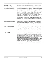
This amplifier generates a mirror image of the programmable reference
voltage about the analog virtual ground (+1.25V) potential. For example,
if the programmable reference voltage output is set to +0.5V with respect
to analog ground (+1.75V absolute), the reference voltage inverter circuit
will generate -0.5V with respect to analog ground (+0.75V absolute). This
allows pace detection algorithm software that executes on the
microcontroller to use the dual voltage comparators as a programmable
“window” comparator. This algorithm monitors the input signal to
determine if it is “inside” or “outside” of the currently set comparator
voltage window. When an input signal pulse of positive or negative
polarity goes outside of the window, the comparator window is made
wider. By measuring the time it takes for the signal to fall outside of this
new comparator voltage window, the algorithm can determine the slew
rate (i.e., rise or fall time) of input signal.
For signals with a slew rate greater than approximately 0.46V/S (volts
per second) the algorithm measures the width of the pulse by measuring
the time it takes for the input signal to fall back inside the comparator
window. The measured pulse width value is then converted to a 7-bit
digital value which is output on the port B I/O pins. The 7-bit digital
value is converted to an analog voltage by an external resistor divider
network that is connected to the inputs of the 10 bit A/D converter
(U100) through a unity gain buffer amplifier (U108).
Digital Circuitry
The digital circuitry consists of microprocessor U5 (sheet 8), EEPROM
U103, watchdog timer U102, and A/D converter U100. The
microprocessor is clocked with a 2.4576-MHz crystal (Y2) which produces
a 1.2288-MHz internal bus speed.
Port A bit 0 (PA0) outputs serial data to the RF drive circuit which drives
the BPSK modulator. Port A also controls the chip enable (CE0*) of the
A/D, EEPROM (PROM_SS*), synthesizer (ENABLE*), and the clock and
data of the synthesizer (U2 on sheet 6). Graph and display switch signals
are input to Port A as PA6 and PA7.
Port B controls crosspoint switch (U101), RF output shutdown
(RF_OUTPUT) and the LL reference switch (SW3_EN).
Port C controls the LEDs which display battery status, lead status, and
pause alarm activation. Port C also controls the RA and LA reference
switches.
Port D communicates with the A/D converter and the EEPROM via the
three serial peripheral interface (SPI) lines (MISO, MOSI, and SCK).
Port D also contains serial communications interface lines (RDI and
TDO) which can be connected to external equipment through the
auxiliary connector (J1).
Watchdog timer U102 provides protection against brown-out (low battery
voltage) and microprocessor failure. It generates a reset whenever the
microprocessor stops executing code properly or when the processor’s
supply voltage drops below a safe operating level.
Содержание Marquette 418793-001
Страница 1: ...APEX Telemetry Transmitter Service Manual 401566 166 Revision D ...
Страница 8: ...CONTENTS vi APEX Telemetry Transmitter Revision D 401566 166 ...
Страница 100: ...TRANSMITTER PCB Schematic Diagram PN SD801278 001A 7 30 APEX Telemetry Transmitter Revision D 401566 166 Sheet 7 of 13 ...
Страница 101: ...TRANSMITTER PCB Schematic Diagram PN SD801278 001A Revision D APEX Telemetry Transmitter 7 31 401566 166 Sheet 8 of 13 ...
Страница 102: ...TRANSMITTER PCB Schematic Diagram PN SD801278 001A 7 32 APEX Telemetry Transmitter Revision D 401566 166 Sheet 9 of 13 ...
Страница 103: ...TRANSMITTER PCB Schematic Diagram PN SD801278 001A Revision D APEX Telemetry Transmitter 7 33 401566 166 Sheet 10 of 13 ...
Страница 104: ...TRANSMITTER PCB Schematic Diagram PN SD801278 001A 7 34 APEX Telemetry Transmitter Revision D 401566 166 Sheet 11 of 13 ...
Страница 105: ...TRANSMITTER PCB Schematic Diagram PN SD801278 001A Revision D APEX Telemetry Transmitter 7 35 401566 166 Sheet 12 of 13 ...
Страница 106: ...TRANSMITTER PCB Schematic Diagram PN SD801278 001A 7 36 APEX Telemetry Transmitter Revision D 401566 166 Sheet 13 of 13 ...
Страница 122: ...OXIMETER ASSEMBLY Parts Location Diagram 421191 001A 8 14 APEX Telemetry Transmitter Revision D 401566 166 Sheet 2 of 3 ...
Страница 123: ...OXIMETER ASSEMBLY Parts Location Diagram 421191 001A Revision D APEX Telemetry Transmitter 8 15 401566 166 Sheet 3 of 3 ...


