
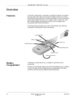

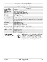

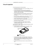


EQUIPMENT OVERVIEW: Overview
Revision D
APEX Telemetry Transmitter
2-3
401566-166
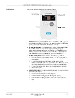
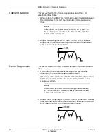
Indicators
The APEX transmitter indicators are described below.
•
CHANGE BATTERY LED. This indicator begins to flash when the
battery voltage level drops below 1.9 Volts. The batteries should be
replaced within 30 minutes after the CHANGE BATTERY LED
begins flashing.
•
GRAPH Control. When this button is pressed the LEAD STATUS
and CHANGE BATTERY LEDs flash twice to acknowledge the
action. Also the graph command is sent to the receiving system to
trigger a graph run.
•
VERIFY LEADS control. When this button is pressed the LEAD
status and CHANGE BATTERY LEDs flash twice to acknowledge
the action. Then the lead status is displayed by these LEDs for 1
minute. The LEDs representing good ECG leads remain illuminated
for the 1 minute period. Bad leads are identified by the associated
LED being turned off.
•
LEAD STATUS LEDs. When the VERIFY LEADS control is pressed,
these LEDs are illuminated if the associated lead signal is good.
•
PAUSE ALARMS LED. Pressing both the VERIFY LEADS and the
GRAPH controls simultaneously results in an alarm pause condition
(in which the alarms are disabled) and the PAUSE ALARMS LED
starts flashing. This condition lasts for 5 minutes.
•
When the PAUSE ALARMS LED stops flashing the condition is over.
•
To end the pause alarms condition prematurely, both the VERIFY
LEADS control and GRAPH controls are pressed again.
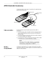
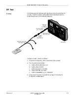
Interface Port
This connector is used to connect the transmitter to the APEX
Programming Device. The TTX number and desired reference lead are
programmed using the APEX Programming Device.
This connector may also be used to connect additional parameter devices
to the APEX transmitter. Refer to “Accessories” on the following pages
for more information.
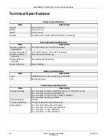
Transmitter Versions
There are four versions the APEX S transmitter assembly.
Upper Level
Part Number Frequency Type
Frequency Range
418793-001
VHF for U.S.
174.05 to 215.95 MHz
418793-002
VHF international
216.00 to 242.00 MHz
418793-003
VHF for U.K.
173.30, 173.75, 173.85, 173.95 MHz
418793-004
UHF international
430.00 to 474.00 MHz
Содержание Marquette 418793-001
Страница 1: ...APEX Telemetry Transmitter Service Manual 401566 166 Revision D ...
Страница 8: ...CONTENTS vi APEX Telemetry Transmitter Revision D 401566 166 ...
Страница 100: ...TRANSMITTER PCB Schematic Diagram PN SD801278 001A 7 30 APEX Telemetry Transmitter Revision D 401566 166 Sheet 7 of 13 ...
Страница 101: ...TRANSMITTER PCB Schematic Diagram PN SD801278 001A Revision D APEX Telemetry Transmitter 7 31 401566 166 Sheet 8 of 13 ...
Страница 102: ...TRANSMITTER PCB Schematic Diagram PN SD801278 001A 7 32 APEX Telemetry Transmitter Revision D 401566 166 Sheet 9 of 13 ...
Страница 103: ...TRANSMITTER PCB Schematic Diagram PN SD801278 001A Revision D APEX Telemetry Transmitter 7 33 401566 166 Sheet 10 of 13 ...
Страница 104: ...TRANSMITTER PCB Schematic Diagram PN SD801278 001A 7 34 APEX Telemetry Transmitter Revision D 401566 166 Sheet 11 of 13 ...
Страница 105: ...TRANSMITTER PCB Schematic Diagram PN SD801278 001A Revision D APEX Telemetry Transmitter 7 35 401566 166 Sheet 12 of 13 ...
Страница 106: ...TRANSMITTER PCB Schematic Diagram PN SD801278 001A 7 36 APEX Telemetry Transmitter Revision D 401566 166 Sheet 13 of 13 ...
Страница 122: ...OXIMETER ASSEMBLY Parts Location Diagram 421191 001A 8 14 APEX Telemetry Transmitter Revision D 401566 166 Sheet 2 of 3 ...
Страница 123: ...OXIMETER ASSEMBLY Parts Location Diagram 421191 001A Revision D APEX Telemetry Transmitter 8 15 401566 166 Sheet 3 of 3 ...


