TROUBLESHOOTING: Powerup Selftests
4-6
APEX Telemetry Transmitter
Revision D
401566-166
Powerup Selftests
Transmitter
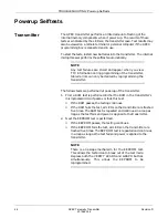
The APEX transmitter performs a limited amount of testing of the
internal memory components when it powers up. The results of these
tests are indicated by the LEDs on the transmitter case. Test results may
also be viewed on a remote terminal or personal computer if the APEX
programming box is connected and in use.
To start the tests, install new batteries into the transmitter. The internal
microprocessor performs the selftests automatically.
NOTE
Any test failures are stored and appear when you view
TTX information during programming of the transmitter.
Stored errors can only be cleared by reprogramming the
transmitter.
The follows tests are performed at powerup of the transmitter.
1.
First a RAM test is performed. Either the RAM in the transmitter’s
microprocessor circuit passes or fails this test.
◆
If the RAM passes, the testing continues.
◆
If the RAM fails the test, all LEDs on the transmitter are flashed
five times. The RAM test is repeated and continues in a loop as
long as the test fails and power is applied to the transmitter.
2.
Next the EEPROM test is performed.
◆
If the EEPROM passes, the testing continues.
◆
If the EEPROM fails the test, all LEDs on the transmitter are
flashed five times. The EEPROM test is repeated and continues
in a loop as long as the test fails and power is applied to the
transmitter.
NOTE
There is an escape mechanism for the EEPROM test.
This allows the technician to break out of the test mode.
Depress both the VERIFY LEADS and GRAPH buttons
simultaneously. This allows the EEPROM to be
reprogrammed.
Содержание Marquette 418793-001
Страница 1: ...APEX Telemetry Transmitter Service Manual 401566 166 Revision D ...
Страница 8: ...CONTENTS vi APEX Telemetry Transmitter Revision D 401566 166 ...
Страница 100: ...TRANSMITTER PCB Schematic Diagram PN SD801278 001A 7 30 APEX Telemetry Transmitter Revision D 401566 166 Sheet 7 of 13 ...
Страница 101: ...TRANSMITTER PCB Schematic Diagram PN SD801278 001A Revision D APEX Telemetry Transmitter 7 31 401566 166 Sheet 8 of 13 ...
Страница 102: ...TRANSMITTER PCB Schematic Diagram PN SD801278 001A 7 32 APEX Telemetry Transmitter Revision D 401566 166 Sheet 9 of 13 ...
Страница 103: ...TRANSMITTER PCB Schematic Diagram PN SD801278 001A Revision D APEX Telemetry Transmitter 7 33 401566 166 Sheet 10 of 13 ...
Страница 104: ...TRANSMITTER PCB Schematic Diagram PN SD801278 001A 7 34 APEX Telemetry Transmitter Revision D 401566 166 Sheet 11 of 13 ...
Страница 105: ...TRANSMITTER PCB Schematic Diagram PN SD801278 001A Revision D APEX Telemetry Transmitter 7 35 401566 166 Sheet 12 of 13 ...
Страница 106: ...TRANSMITTER PCB Schematic Diagram PN SD801278 001A 7 36 APEX Telemetry Transmitter Revision D 401566 166 Sheet 13 of 13 ...
Страница 122: ...OXIMETER ASSEMBLY Parts Location Diagram 421191 001A 8 14 APEX Telemetry Transmitter Revision D 401566 166 Sheet 2 of 3 ...
Страница 123: ...OXIMETER ASSEMBLY Parts Location Diagram 421191 001A Revision D APEX Telemetry Transmitter 8 15 401566 166 Sheet 3 of 3 ...

