Innova 2000 Cardiovascular Imaging System
GE Medical Systems
Pre–Installation Manual
REV 5
pim 2337741–100
119
8
RECOMMENDED POWER DISTRIBUTION SYSTEM
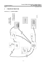
The drawing hereafter is a guide to illustrate all functions included inside
the main disconnect room device.
It should be compliant with the specific country rules.
8-1
Main functions
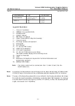
Lock–out/Tag–out by CM, R1 and R,
Main disconnect device by DMD1 and DMD2,
Low voltage created by TR1 applied on remote, L1 and L2,
Separated injection circuit by TR2 and BR,
L is mandatory for French standards,
Protect the Room Emergency Off (AU1, AU2) from accidental activation
L1 is mandatory in several countries. By the same L1 circuit one or many
other(s) light indicator(s) have to be mounted inside the examination room
and have to be visible from anywhere by operators.
It is recommended to separate the two power supply cables from the other
cables.
CAUTION
CAUTION
CAUTION

