Innova 2000 Cardiovascular Imaging System
GE Medical Systems
Pre–Installation Manual
REV 5
pim 2337741–100
52
2-5
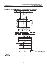
Walls
General requirement
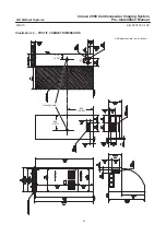
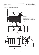
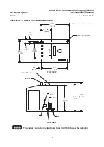
A normal way to mount heavy cabinets such as ACAB Cabinet, POSTIT Cabinet and X–Ray
Generator Cabinet is to securely fasten them to the wall to prevent them from tipping.
Seismic Areas
Consider local seismic codes when planning cabinet mounting. Consult seismic expert to determine
which mounting method is appropriate for the seismic region. Certain seismic regions require
additional reinforcement in walls. See Chapter 2 – System compatibilities for referential documents.
3
ELECTRICAL REQUIREMENTS
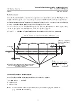
Innova System requires three specific power lines, one for the X–Ray Generator, one for the
Cabinets, and one for the Chillers (see Illustration 52).
Connect the main power demand to the X–Ray generator.
X–Ray generator is feed by a 126 kVA three phase power line.
For Generator Power Supply Features, see ref 60601.1 IEC.
Table 21 – ELECTRICAL REQUIREMENTS: System line voltage
PHASES
VOLTS
I inrush
CURRENT
COS PHI
FREQ
Cabinet
3Ø
400 V – 480 V
+ 10 % – 5 %
280 A
0.1 sec
28 A
0.95
50 – 60 Hz
3 Hz
X–Ray generator
(see note below)
3Ø
380 V – 480 V
10 %
380: 191 A
480: 151 A
380: 16 A
480: 14 A
0.8
50 – 60 Hz
3 Hz
CHILLER
3Ø
380 V – 480 V
10 %
3 second 15 %
48 A
5.5 A (50 Hz)
6.8 A (60 Hz)
0.95
50 – 60 Hz
Line impedance should be compliant with IEC 601.2.7
Refer to the table paragraph NO TAG, page NO TAG.
4
GROUNDING
A minimum of 35 square millimeter (AWG2) copper wire is mandatory from Hospital Vault to ACAB
Cabinet.
The ground cable inserted between the PDB (Main Disconnect Panel) and the X–Ray generator
Cabinet can be reduced to a nominal of 25 square millimeter (or AWG2) compliant with size of plugs.
(From AWG4 to AWG0) common with feed cables.
Refer to Illustration 53, page 116.
NOTICE

