


Innova 2000 Cardiovascular Imaging System
GE Medical Systems
Pre–Installation Manual
REV 5
pim 2337741–100
49
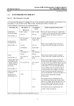
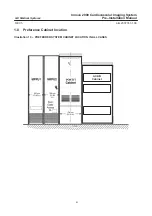
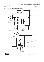
2-4
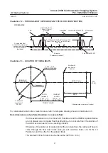
Ceiling
Aluminum rails support the In–Room TV Monitor bridge used in Innova 2000 system X–ray rooms.
Reference
For additional details on ceiling requirements for stationary rails, refer to:
Direction 46–019639,
Advantx (VHLA) XT Stationary Rails Installation and
Adjustment.
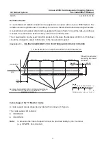
When evaluating ceiling you must take into account the following mounting information:
Rail Mounting
Attach stationary rails to structural steel with through-bolts in concrete ceilings. Do not use screw
anchors in direct tension.
Mount stationary rails directly to the ceiling slab or to flush–mounted unistrut or halfen structure. In
higher rooms with false ceiling, mount stationary rails to rigid vertical members hung from ceiling slab.
Securing a supplementary channel to the bottom of the vertical members and mounting the stationary
rails to this channel can greatly reduce the number of vertical members.
The stationary rail support structure must be leveled before installation can begin. Do not assume that
any support structure is level within specified tolerances, particularly after removing suspensions
from an existing room.
Bolt Specifications
The maximum load per bolt will not exceed 1557 N.
Each bolt must not “pull out” or otherwise fail under a vertically downward “dead” load of 6227 N.
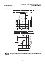
Select Rails
All XT Stationary rails are with a select length process. Detail of available length is illustrated in
Chapter 7, Section 5.
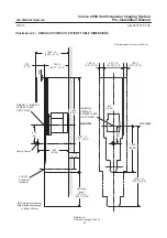
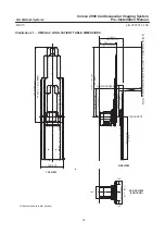
Boom Mounted for TV Suspension
One type of boom mounted is supplied as counterpoised monitor suspension not adjusted on site as
follows:
for 2 x 21” (53 cm) VEGA 21” (HI–bright) and additional ECG monitor.