CHAPTER 2: INSTALL ATION/CONFIGURATION
2.52
EP OS MOTOR MANAGEMENT SYSTEM – INSTRUCTION MANUAL
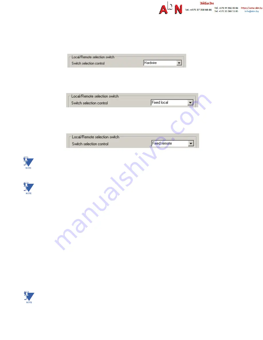
If Hardwire is selected as a controlling device, one input must be mapped to mode switch local and a different input to
mode switch remote. If input mode switch local is active, all mechanisms defined as locals can control the motor
(ON/OFF). If input mode switch remote is active, the mechanism defined as remote can control the motor (ON/OFF).
If Fixed local is selected as a controlling device, any source assigned as local can control the motor (ON/OFF).
If Fixed remote is selected as a controlling device, only the remote source can control the motor (ON/OFF).
NOTE:
O
nly one control (local or remote) can be enabled at a time. If both (local and remote) are active the “drawer
ready switch” will be OFF and the motor cannot start.
NOTE:
T
o make any changes on the configuration, “parameter allowed” must be enabled in WinESG
parameterization/function panel or Modbus function code 6 register 62.
Refer to section 2.2.1 for the motor control detailed configuration.
Breaker control operation:
When a start function ON1 is received, contactor K1, controlled by EntelliPro output relay 41,
will close for pre-defined time, defined as “breaker open/close signal time” in WinESG parameterization/timer panel or
Modbus function code 6 register 37. When this timer expires, contact output relay K1 opens.
When a stop function is received, contactor K2, controlled by EntelliPro ES output relay 43, will close for a pre-defined
timer defined as “breaker open/close signal time” in WinESG parameterization/timer panel or Modbus function code 6
register 37. When the timer expires, contact output 43 opens.
Refer to Tables 2-6 and 2-7 for the complete input, output, timer and control configurations of breaker control motor
starter.
Figure-s 222 and 2-23 show typical breaker control motor starter diagrams for EntelliPro ES3 and EntelliPro ES5.
NOTE:
I
nterpoling CTs are required for higher than 630Amps system.
Содержание EntelliPro ES Series
Страница 2: ...This page was intentionally left blank ...
Страница 8: ...This page was intentionally left blank ...
Страница 182: ...CHAPTER 4 COMMUNICATION EPOS MOTOR MANAGEMENT SYSTEM INSTRUCTION MANUAL 4 45 This page was intentionally left blank ...
Страница 255: ...EPOS MOTOR MANAGEMENT SYSTEM INSTRUCTION MANUAL 6 20 CHAPTER 6 ENTELLIPRO CP3 and CP5 APPLICATION ...


