2 Theory of Operation
M1046983 04/08
2-21
Summary of the
Anesthesia Controller
Board
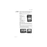
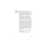
The Anesthesia Controller Board is the central controller for the system. It provides the
following services:
• Monitors pressures form the pipeline and cylinder transducers.
• Drives some of the valves located on the Electronic Gas Mixer.
• Monitors the Alt O2 Switch.
• Provides 10VA limited power and communication to the following subsystems:
• Ventilator Interface Board (VIB)
• Electronic Gas Mixer
• Agent Delivery Board (ADB)
• Provides 10VA limited power (no communication) to the M-Gas Power Board
The Anesthesia Controller Board receives power from the PCB on connector J6.
The Anesthesia Controller Board creates internal voltages that remain local to and are
used exclusively by circuits on the Anesthesia Controller Board. These voltages are:
• 3.3 VDC
• 1.8 VDC (Processor and Digital)
• 2.5 VDC
• 5 VDC (Gas Pressure Transducers)
The Anesthesia Controller Board also creates fourteen independent 12VDC 10VA
limited power sources used by the following subsystems:
• 10VA M-Gas
• 10VA Mixer
• 10VA eVap ADB Power
• 10VA eVap Outflow, Scavenging Power
• 10VA eVap Proportional Valve Power
• 10VA eVap Inflow, Zero Valve Power
• 10VA O
2
Bypass Valve
• 10VA Ventilator Interface Board
• 10VA Vent Valve Power
• 10VA Accessories
• 10VA Mixer / Pan Fan
• 10VA External Peripheral # 1
• 10VA External Peripheral # 2
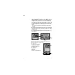
The Anesthesia Controller Board has eight status LEDs. Each LED Status is duplicated
on the board. Six are yellow status and two are red reset.
The TXD and RXD flash to indicate communication to and from the Display Unit. A RED
LED would indicate a CPU watchdog (RESET) condition.
The Anesthesia Controller Board receives communication from the Display Unit,
Electronic Vaporizer, Electronic Gas Mixer, and Ventilator Engine Board. It has a hand in
virtually all-major decisions about the delivery of gas, ventilation, and agent to the
patient.
Содержание Datex-Ohmeda Aisys Carestation
Страница 1: ...Aisys Anesthesia Machine Technical Reference Manual ...
Страница 16: ...Notes xiv 04 08 M1046983 ...
Страница 32: ...Notes 1 16 04 08 M1046983 ...
Страница 35: ...2 Theory of Operation M1046983 04 08 2 3 A M AB 75 098 L H D AB 75 046 J G I F K P O E D B C H N ...
Страница 158: ...Notes 5 20 04 08 M1046983 ...
Страница 288: ...Notes 7 106 04 08 M1046983 ...
Страница 325: ...9 Repair Procedures M1046983 04 08 9 29 The rear inverter A B C ...
Страница 356: ...Notes 9 60 04 08 M1046983 ...
Страница 397: ...10 Illustrated Parts M1046983 04 08 10 41 1 3 4 2 17 15 16 5 6 13 non DES cassette DES cassette 7 8 11 12 10 5 14 18 9 ...
Страница 399: ...10 Illustrated Parts M1046983 04 08 10 43 14 1 2 3 6 5 4 5 8 7 15 16 15 12 17 10 9 11 13 or 18 ...
Страница 401: ...10 Illustrated Parts M1046983 04 08 10 45 14 1 2 3 6 5 4 5 8 7 15 16 18 17 10 9 11 12 13 or ...
Страница 403: ...10 Illustrated Parts M1046983 04 08 10 47 14 15 18 1 2 3 6 5 4 5 8 7 17 10 9 11 15 16 12 13 or 17a 17c 17d 17b 17e ...
Страница 452: ...Notes 10 96 04 08 M1046983 ...
Страница 466: ...11 14 04 08 M1046983 Notes ...
Страница 470: ...Aisys 12 4 04 08 M1046983 12 3 System Schematics 12 3 1 Power Schematic ...
Страница 478: ...Aisys 12 12 04 08 M1046983 12 6 3 Tools Transfer Logs ...
Страница 495: ...12 Service Application M1046983 04 08 12 29 12 10 2 Vaporizer Subsystem Perform Vaporizer Test ...
Страница 497: ......

