7 Troubleshooting
M1046983 04/08
7-57
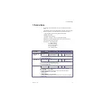
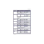
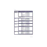
FLOW VERIFICATION
FAILURE (dP) CH1
Indicates the commanded
flow through the O2 Gas
Channel and the flow
measured by the Hot-wire
anemometer agrees but the
flow as measured by the
pressure transducers does
not agree.
Mixer
Perform the Mixer zero.
Replace Mixer.
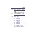
FRONT PANEL COM
FAIL
Display panel controls
failure
Key pad controller fails to
send “life tick” for greater
than 10 Sec.
Medium
(Yellow)
DC
Reboot system. If problem continues, replace Display Controller Board.
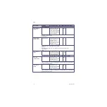
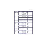
GAS INLET VALVE
BOOTUP TEST FAIL
Vent Fail. Monitoring
Only
Boot-up test failed.
High
AC,
Vent
1. Check GIV solenoid connection.
2. Replace GIV.
3. Rebuild the GIV components.
4. Replace VIB.
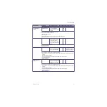
INFLOW CHECK VALVE
FAILURE
Vaporizer Failure
Negative flow in the cassette
inflow limb greater than limit.
AC
Replace Inflow check valve.
(Also see Section 7.10.)
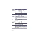
INFLOW OUTFLOW
CROSSCHECK FAILURE
INFLOW OUTFLOW
CROSSCHECK FAILURE
RECOVERABLE
Vaporizer Failure
Output concentration
measured by the output and
input flowmeter disagree by
more than limit.
AC
Check eVap and cassettes used with the machine for leaks.
Replace and retest in the following order (Also see Section 7.10.):
• Zero Valve (Inflow or Outflow depending on Vaporizer Test results).
• Flowmeter Block
• ADB
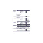
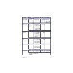
INSP FLOW SENSOR
CAL ERROR
Calibrate flow sensors
Insp Flow Sensor zero offset
out of range.
Low
AC,
Vent
Flow sensor detected
In the Service Software / Vent Flow and Pressure Diagnostics, verify the Inspiratory Pressure counts is
2050 ± 250.
Disconnect the Black and White in-line connectors. If the counts return within specified range, check for
occlusions in the Bulkhead harness.
If the counts do not return within the specified range, replace the VIB.
Error Log Entry
Alarm Text
Condition (Basic info)
Priority Source Enabling Criteria
Action/Troubleshooting
Содержание Datex-Ohmeda Aisys Carestation
Страница 1: ...Aisys Anesthesia Machine Technical Reference Manual ...
Страница 16: ...Notes xiv 04 08 M1046983 ...
Страница 32: ...Notes 1 16 04 08 M1046983 ...
Страница 35: ...2 Theory of Operation M1046983 04 08 2 3 A M AB 75 098 L H D AB 75 046 J G I F K P O E D B C H N ...
Страница 158: ...Notes 5 20 04 08 M1046983 ...
Страница 288: ...Notes 7 106 04 08 M1046983 ...
Страница 325: ...9 Repair Procedures M1046983 04 08 9 29 The rear inverter A B C ...
Страница 356: ...Notes 9 60 04 08 M1046983 ...
Страница 397: ...10 Illustrated Parts M1046983 04 08 10 41 1 3 4 2 17 15 16 5 6 13 non DES cassette DES cassette 7 8 11 12 10 5 14 18 9 ...
Страница 399: ...10 Illustrated Parts M1046983 04 08 10 43 14 1 2 3 6 5 4 5 8 7 15 16 15 12 17 10 9 11 13 or 18 ...
Страница 401: ...10 Illustrated Parts M1046983 04 08 10 45 14 1 2 3 6 5 4 5 8 7 15 16 18 17 10 9 11 12 13 or ...
Страница 403: ...10 Illustrated Parts M1046983 04 08 10 47 14 15 18 1 2 3 6 5 4 5 8 7 17 10 9 11 15 16 12 13 or 17a 17c 17d 17b 17e ...
Страница 452: ...Notes 10 96 04 08 M1046983 ...
Страница 466: ...11 14 04 08 M1046983 Notes ...
Страница 470: ...Aisys 12 4 04 08 M1046983 12 3 System Schematics 12 3 1 Power Schematic ...
Страница 478: ...Aisys 12 12 04 08 M1046983 12 6 3 Tools Transfer Logs ...
Страница 495: ...12 Service Application M1046983 04 08 12 29 12 10 2 Vaporizer Subsystem Perform Vaporizer Test ...
Страница 497: ......

