11 Schematics and Diagrams
M1046983 04/08
11-7
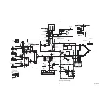
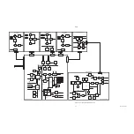
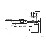
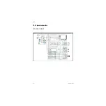
Figure 11-6 • System block diagram (sheet 2 of 3)
Electronic
Gas Mixer
O2
Temp
Sense
O2
Flow
Sense
O2 Prop
Vlv
Bal Gas
Temp
Sense
Bal Gas
Flow
Sense
Bal Gas
Prop
Vlv
Total
Flow
Sense
Total
p sense
Total
Flow
t sense
Atmel Microcontroller
ADC Ref
Check
O2
Sel Valve
N2O
Sel Valve
Air
Sel Valve
O2 Byp
Sel Valve
ABS
Filter Board
A
CGO Solenoid
O2-Flush S
W
A
CGO/SCGO S
W
Vent
Engine
Connector
Board
Sh1
Sh1
Flo
w
Contr
ol
GIV
ABS F
ilter
Boar
d
Vent
Engine
ABS S
W
Bag V
ent S
W
O2 Sensor
Canis
ter R
elease S
W
Insp Flo
w
Exp Flo
w
Sensor
Task Light
A
cc Po
w
er
VIB
Pan Connector Boar
d
Amp/Filter
Amp/Filter
Amp/Filter
Amp/Filter
RS-422
Transceiver
P
a
n
C
o
n
n
e
c
to
r
B
o
a
rd
+6.0VA
-6.0VA
ATMEGA16
Microcontroller
+5.0VDD
+5.0VA
ADC
12-Bit
8-Channel
Local Power
Supply
Regulators
+12.5V
I
2
C MUX
to Flow Sensors
Insp Data
Bag/Vent Sw
O2 Disconnect
O2 Flush Sw
DAC
12-Bit
SCGO On
GIV On
I
2
C
M
U
X
S
e
l
E
2
P
w
r
O
n
Amp/Filter
Fl
o
w
D
A
C
F
B
VDD Over-
Voltage Monitor
RxD
TxD
O2
S
ign
al
E
2
+5.0V
Watchdog and
Under-Voltage
Monitor
ADC
10-Bit
S
P
I
P
o
rt
Parallel I/O
Flow
Valve
Driver
GIV
Driver
SCGO
Driver
Exp Data
I
2
C
P
o
rt
ACGO/SCGO Sw
ABS On Sw
Comp
3.
2
V
RE
F
VREF
Ov
e
r_
P
re
s
s
Over_Press
O2 Sensor
E
2
Clk
+12.5V Accessory Power
+12.5V Valve Power
F
lo
w
D
ri
v
e
F
B
SPI Addr
Decoder
FL DAC CS
FL DAC LD
ADC CS
SPI
A
DD
R0
SPI
A
DD
R1
DA
C
L
D
SPI
C
S
ISP
Header
Emulator
Header
E
2
GND
CGO Sw
Filter
Local Power
Supply Monitors
+12.5V
Reset
A
n
a
lo
g
T
e
s
t
C
o
n
n
e
c
to
r
Inspiratory
Transducer
Expiratory
Transducer
Manifold
Transducer
Airway
Transducer
Over_Press
+12.5V
Airway_Press
Manifold_Press
Inspiratory_Press
Expiratory_Press
GIV Drv
SCGO
Activity Indicators
Reset, Watchdog,
Txd & Rxd
W_Dog
+5V
Reg.
Ventilator Interface Board
ABS Filter Board
Canister Release Sw
AB.75.024
Содержание Datex-Ohmeda Aisys Carestation
Страница 1: ...Aisys Anesthesia Machine Technical Reference Manual ...
Страница 16: ...Notes xiv 04 08 M1046983 ...
Страница 32: ...Notes 1 16 04 08 M1046983 ...
Страница 35: ...2 Theory of Operation M1046983 04 08 2 3 A M AB 75 098 L H D AB 75 046 J G I F K P O E D B C H N ...
Страница 158: ...Notes 5 20 04 08 M1046983 ...
Страница 288: ...Notes 7 106 04 08 M1046983 ...
Страница 325: ...9 Repair Procedures M1046983 04 08 9 29 The rear inverter A B C ...
Страница 356: ...Notes 9 60 04 08 M1046983 ...
Страница 397: ...10 Illustrated Parts M1046983 04 08 10 41 1 3 4 2 17 15 16 5 6 13 non DES cassette DES cassette 7 8 11 12 10 5 14 18 9 ...
Страница 399: ...10 Illustrated Parts M1046983 04 08 10 43 14 1 2 3 6 5 4 5 8 7 15 16 15 12 17 10 9 11 13 or 18 ...
Страница 401: ...10 Illustrated Parts M1046983 04 08 10 45 14 1 2 3 6 5 4 5 8 7 15 16 18 17 10 9 11 12 13 or ...
Страница 403: ...10 Illustrated Parts M1046983 04 08 10 47 14 15 18 1 2 3 6 5 4 5 8 7 17 10 9 11 15 16 12 13 or 17a 17c 17d 17b 17e ...
Страница 452: ...Notes 10 96 04 08 M1046983 ...
Страница 466: ...11 14 04 08 M1046983 Notes ...
Страница 470: ...Aisys 12 4 04 08 M1046983 12 3 System Schematics 12 3 1 Power Schematic ...
Страница 478: ...Aisys 12 12 04 08 M1046983 12 6 3 Tools Transfer Logs ...
Страница 495: ...12 Service Application M1046983 04 08 12 29 12 10 2 Vaporizer Subsystem Perform Vaporizer Test ...
Страница 497: ......


