6 Installation and Maintenance
M1046983 04/08
6-13
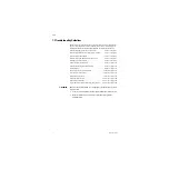
6.9 Integrated Suction Regulator tests
Note
There are two types of integrated suction systems for the Avance anesthesia
machine:
• Continuous Vacuum Regulator, Three-Mode, Pipeline Vacuum
• Continuous Vacuum Regulator, Three-Mode, Venturi Derived Vacuum
For Pipeline Vacuum systems
,
a vacuum source of at least 500 mm Hg (67 kPa or 20 in Hg) is required for
testing. The supply open flow must be a minimum of 50 L/min.
For Venturi Derived Vacuum systems,
an O
2
or Air source of at least 282 kPa (41 psi) is required for testing.
Gauge Accuracy
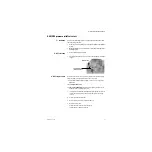
The gauge needle should come to rest within the zero range bracket when no
suction is being supplied. Gauges which do not comply may be out of
tolerance.
Note
To check gauge accuracy, be sure that the test gauge is capable of measuring
0 to 550 mm Hg with an accuracy of ±1% of reading.
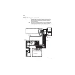
1. Connect the suction patient port to the test gauge.
2. Turn the mode selector switch to I (ON).
3. Ensure that the vacuum test gauge is in agreement with the suction vacuum
gauge ± 38 mm Hg/5 kPa at the following test points.
Flow Test
Note:
To check flow accuracy, be sure that the flow test device is capable of
measuring 0–30 L/min with an accuracy of ± 2% of reading.
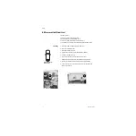
1. Connect the patient port of the suction regulator to the flow test device.
2. Rotate the suction control knob fully clockwise (increase).
3. Turn the mode selector switch to I (ON) and verify that the flow rate is:
• at least 20 L/min.
4. Disconnect the test flowmeter.
(Tests continue on next page.)
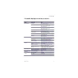
Test points
Suction vacuum gauge
Test gauge tolerance
100 mm Hg (13.3 kPa)
62–138 mm Hg (8.3–18.4 kPa)
300 mm Hg (40 kPa)
262–338 mm Hg (35–45 kPa)
500 mm Hg (66.7 kPa)
462-538 mm Hg (61.6–71.7) kPa)
Содержание Datex-Ohmeda Aisys Carestation
Страница 1: ...Aisys Anesthesia Machine Technical Reference Manual ...
Страница 16: ...Notes xiv 04 08 M1046983 ...
Страница 32: ...Notes 1 16 04 08 M1046983 ...
Страница 35: ...2 Theory of Operation M1046983 04 08 2 3 A M AB 75 098 L H D AB 75 046 J G I F K P O E D B C H N ...
Страница 158: ...Notes 5 20 04 08 M1046983 ...
Страница 288: ...Notes 7 106 04 08 M1046983 ...
Страница 325: ...9 Repair Procedures M1046983 04 08 9 29 The rear inverter A B C ...
Страница 356: ...Notes 9 60 04 08 M1046983 ...
Страница 397: ...10 Illustrated Parts M1046983 04 08 10 41 1 3 4 2 17 15 16 5 6 13 non DES cassette DES cassette 7 8 11 12 10 5 14 18 9 ...
Страница 399: ...10 Illustrated Parts M1046983 04 08 10 43 14 1 2 3 6 5 4 5 8 7 15 16 15 12 17 10 9 11 13 or 18 ...
Страница 401: ...10 Illustrated Parts M1046983 04 08 10 45 14 1 2 3 6 5 4 5 8 7 15 16 18 17 10 9 11 12 13 or ...
Страница 403: ...10 Illustrated Parts M1046983 04 08 10 47 14 15 18 1 2 3 6 5 4 5 8 7 17 10 9 11 15 16 12 13 or 17a 17c 17d 17b 17e ...
Страница 452: ...Notes 10 96 04 08 M1046983 ...
Страница 466: ...11 14 04 08 M1046983 Notes ...
Страница 470: ...Aisys 12 4 04 08 M1046983 12 3 System Schematics 12 3 1 Power Schematic ...
Страница 478: ...Aisys 12 12 04 08 M1046983 12 6 3 Tools Transfer Logs ...
Страница 495: ...12 Service Application M1046983 04 08 12 29 12 10 2 Vaporizer Subsystem Perform Vaporizer Test ...
Страница 497: ......

