Aisys
9-30
04/08 M1046983
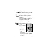
9.11.8 To replace
the front
enclosure or
components
Disassemble the Display Unit following procedures in the previous sections to the point
where you have removed the mounting plate assembly from the front enclosure.
If you are replacing the front enclosure, you can transfer the encoder (12) assembly to
the new enclosure; but, you must build up the replacement enclosure with:
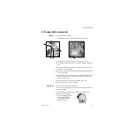
• a new window (11)
• new membrane switches — right-side (14), lower (15), left-side (16)
• new keypads - right-side (17), lower (18), left-side (19)
• new EMC gasket (10)
If you are replacing a keypad or a membrane switch, you must replace both items.
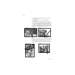
To replace the window
1. Place the front enclosure face up on a flat surface.
2. Press down on one corner of the window to free it from the enclosure.
3. Work your way around the window until you can get a hold of it from the back.
4. Slowly pry the window from the enclosure.
5. Place the front enclosure face down on a flat surface, taking care not to damage the
encoder.
6. Remove any remaining residue from the mounting area; clean with isopropyl
alcohol.
7. Remove the inside protective material from the front of the window.
8. Peel the front outside frame of the release liner.
9. Lower the window straight down in the enclose, noting the notch in the window and
the matching nub on the enclosure.
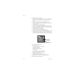
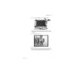
10.Before seating the window, position it in contact with the bottom and right sides of
the frame (see arrows) so that the larger gap between the window and the enclosure
is at the top and left edges (as viewed from behind).
11.Remove the protective film from the back side of the window.
(11)
(14, 17)
(12)
(15, 18)
(16, 19)
Nub
(10)
Содержание Datex-Ohmeda Aisys Carestation
Страница 1: ...Aisys Anesthesia Machine Technical Reference Manual ...
Страница 16: ...Notes xiv 04 08 M1046983 ...
Страница 32: ...Notes 1 16 04 08 M1046983 ...
Страница 35: ...2 Theory of Operation M1046983 04 08 2 3 A M AB 75 098 L H D AB 75 046 J G I F K P O E D B C H N ...
Страница 158: ...Notes 5 20 04 08 M1046983 ...
Страница 288: ...Notes 7 106 04 08 M1046983 ...
Страница 325: ...9 Repair Procedures M1046983 04 08 9 29 The rear inverter A B C ...
Страница 356: ...Notes 9 60 04 08 M1046983 ...
Страница 397: ...10 Illustrated Parts M1046983 04 08 10 41 1 3 4 2 17 15 16 5 6 13 non DES cassette DES cassette 7 8 11 12 10 5 14 18 9 ...
Страница 399: ...10 Illustrated Parts M1046983 04 08 10 43 14 1 2 3 6 5 4 5 8 7 15 16 15 12 17 10 9 11 13 or 18 ...
Страница 401: ...10 Illustrated Parts M1046983 04 08 10 45 14 1 2 3 6 5 4 5 8 7 15 16 18 17 10 9 11 12 13 or ...
Страница 403: ...10 Illustrated Parts M1046983 04 08 10 47 14 15 18 1 2 3 6 5 4 5 8 7 17 10 9 11 15 16 12 13 or 17a 17c 17d 17b 17e ...
Страница 452: ...Notes 10 96 04 08 M1046983 ...
Страница 466: ...11 14 04 08 M1046983 Notes ...
Страница 470: ...Aisys 12 4 04 08 M1046983 12 3 System Schematics 12 3 1 Power Schematic ...
Страница 478: ...Aisys 12 12 04 08 M1046983 12 6 3 Tools Transfer Logs ...
Страница 495: ...12 Service Application M1046983 04 08 12 29 12 10 2 Vaporizer Subsystem Perform Vaporizer Test ...
Страница 497: ......


