Note:
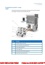
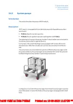
Avoid locking the pump wagon wheels when the wagon is pinlocked under
the system if the system is intended to be moved.
A pump needs an open flow path, and the switch set to Run, to receive a start signal.
For instructions on how to fit the pump chamber to the motor see
disposable flow kits, on page 97
For specifications refer to the General specification or the manufacturer's user docu-
mentation the in the documentation package provided with the delivery.
CAUTION
The pump wagon must be located under the system during oper-
ation.
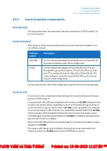
High pressure safety monitoring
The system is designed to be protected from exceeding the high pressure limit by an
electronic Safety PLC module located inside the cabinet. The module monitors the
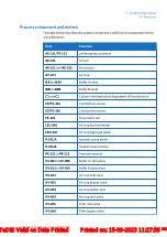
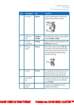
pressure in the pressure transmitters connected to PE-111 to PE-113. The output
values of the transmitters are hardwired to the safety module.
If any of the monitored parameters reaches a critical limit, the safety module shuts
down the pumps independently from the software control system and an alarm
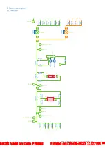
alerts the user. For more information see the section below and the Piping and In-
strumentation Diagram provided in the documentation package.
Note:
The Safety PLC module that monitors the system operating pressure is a
protection for the system and not the column. If the pressure limit of
the column is lower than that of the system, the high pressure alarm set-
tings in the software control system must be changed accordingly.
Column protection from overpressure can be accomplished, for example,
by adding a relief valve or burst disc before the column.
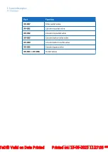
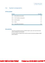
3 System description
3.4 System components
3.4.3 System pumps
52
ÄKTA ready XL Operating Instructions 29281616 AE
*** TeDIS Valid on Date Printed Printed on: 15-09-2023 11:27:35 ***

