background image

IF 632 Installation and Operation Manual 


Release: 3 01/31/01 

 93 

SYSTEM RESTART / RE-CONFIGURATION - SMARTSTART 

∆∆∆∆

 WARNING ! 


All programming data will be lost when the system is re-
configured.  The system will initialize the SmartStart


feature and will configure a new data base. 

Hardware Reset 

1.  Complete a hardware reset by shorting the jumper pins on P4, located on the CPU card.  Figure 2 

screen will be displayed.  (Power On/System Reset) 

2.  While the Power On LED is still flashing, press the [

ACK

] switch.  Figure 3 will be displayed. 


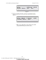
Password Entry Screen 

 
Enter Password: 
Security Level: X


User ID: XXX 

Figure 3 

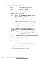
3.  Enter a Level 4 password. If an invalid password is entered, or no password is entered, the 

system will go into normal reset and skip the SmartStart. 

4.  If the password is accepted Figure 3A will be displayed. If no action is taken the system will continue 

its reset process. 


To Initialize System to Default settings 

Press Enter Key Now 

All Programmed Data will be lost !!!! 

Figure 3A 

∆∆∆∆

 WARNING ! 


Pressing "Enter" - all programmed data will be lost.  
Pressing any other key will Bypassed the re-configuration 
sequence. 


5.  Press "

Enter

" to begin SmartStart processing.  Figure 3A is displayed.  "Time remaining 

N

 sec" is 

a countdown from 15 seconds. 


Status : Normal                               00/00/94  00:00 

Begin System I/O Assignments. 

 Please Wait .... 15 sec   Power Up Delay ! 

Time remaining N sec 

Figure 3B 


Technical Manuals Online! - http://www.tech-man.com

firealarmresources.com

Содержание IDENTIFLEX 632

Страница 1: ...SABLE FIRE ALARM CONTROL PANEL Installation Operation Manual The Gamewell Company P N 71906 60 Pleasant St Release 3 1 31 2001 Ashland MA 01721 Firmware Ver 7 Technical Manuals Online http www tech ma...

Страница 2: ...IF 632 Installation and Operation Manual Release 3 01 31 01 ii This page intentionally blank Technical Manuals Online http www tech man com firealarmresources com...

Страница 3: ...s proprietary to The Gamewell Company Such information and technical drawings may not be copied or reproduced in any manner or disclosed to organizations that might be competitive to Gamewell without...

Страница 4: ...IF 632 Installation and Operation Manual Release 3 01 31 01 iv This page intentionally blank Technical Manuals Online http www tech man com firealarmresources com...

Страница 5: ...mage to the equipment we suggest using all Gamewell Components 4 There is no substitute for proper maintenance and testing of this or any life safety product Gamewell recommends testing and maintenanc...

Страница 6: ...IF 632 Installation and Operation Manual Release 3 01 31 01 vi This page intentionally blank Technical Manuals Online http www tech man com firealarmresources com...

Страница 7: ...ilding Control Display Placement 15 Walk Test Auto Terminate 16 RELEASING 16 SYSTEM OVERVIEW 18 IF 632 Control Panel 18 Modular Construction 18 SmartStart 18 SYSTEM MODULAR CONSTRUCTION 19 Common Cont...

Страница 8: ...l Circuit Module Terminal Description 57 Class A Adapter Universal Signal Module Terminal Description 57 Relay Module 58 Relay Module 59 Relay Expansion Module 59 Building Control Module 59 Building C...

Страница 9: ...97 Device Selection 98 Heat Device Operating Selection 98 Zone Type Selection 99 Initiating Group Selection 99 User Text Selection 99 Output Circuit Programming 101 Field Descriptions for Signal Circ...

Страница 10: ...126 Change Trbl 127 Change Bldg Control Switch Supervision 127 Change Day Enable 127 Change Day Night Mode 128 Change Abort Type 128 Change Prefix 129 Change Configuration Name 129 Change Tally Count...

Страница 11: ...M EVENT MESSAGES 147 F 600 CONFIGURATION FILE DATA STRUCTURE 150 Sample Configuration File 150 Configuration Data Descriptions 154 File Variable 154 System Variables 154 Card Variables 157 Input Devic...

Страница 12: ...IF 632 Installation and Operation Manual Release 3 01 31 01 xii This page intentionally blank Technical Manuals Online http www tech man com firealarmresources com...

Страница 13: ...Section 1 IDENTIFLEX 632 System Description Technical Manuals Online http www tech man com firealarmresources com...

Страница 14: ...IF 632 Installation and Operation Manual Release 3 01 31 01 14 This page intentionally blank Technical Manuals Online http www tech man com firealarmresources com...

Страница 15: ...r Leap Years Including the year 2000 Positive Alarm Sequence Allows Day Night control of the use of PAS Verification Counter Provides a tally of the number of times a Verification point activates with...

Страница 16: ...s the switch is activated Upon deactivation of the switch the counter will resume from where it was paused Only one activation of the Abort switch is recognized Subsequent activations will have no eff...

Страница 17: ...up X Select the input device for the Dump switch program it as a Dump zone and Assign Input Group X Output Devices Select the Signal Circuit Conventional to sound the audible alarm program it s Alarm...

Страница 18: ...nstruction The design of the system utilizes a modular building block approach The base system consists of the Common Control the Main Power Supply and the system cabinet with two card bays and an Ana...

Страница 19: ...rrow keys for scrolling through events and selecting functions Bus Driver Module The bus driver module BDM contains the circuitry that interfaces with the CPU and system modules It is equipped with tw...

Страница 20: ...ut device include the Relay Control Element RCE 95 the Signal Control Element SCE 95 the Building Control Element BCE 95 and the City Tie module CTX 95 ________________________________________________...

Страница 21: ...output module These modules are available in either 4 circuit USM 4 or 8 circuit USM 8 increments These circuits are designed to meet the requirements of NFPA 72 Style Y Class B notification applianc...

Страница 22: ...___________________________________________________________ AM500 Module The AM500 module allows the IF632 system to interface to Flex 500 devices It has been designed with 8 Class B circuits that wil...

Страница 23: ...ery Charger Module The battery charger module is a plug in type module that installs directly into the main power supply This module will monitor and recharge lead acid batteries from 5 to 60 Amp hour...

Страница 24: ...IF 632 Installation and Operation Manual Release 3 01 31 01 24 This page intentionally blank Technical Manuals Online http www tech man com firealarmresources com...

Страница 25: ...Section 2 IDENTIFLEX 632 System Operation Technical Manuals Online http www tech man com firealarmresources com...

Страница 26: ...IF 632 Installation and Operation Manual Release 3 01 31 01 26 This page intentionally blank Technical Manuals Online http www tech man com firealarmresources com...

Страница 27: ...uthority having jurisdiction has authorized reset Reset Switch The Reset switch RESET removes power from the initiating devices for a period of four 4 seconds Power is temporarily removed from the S S...

Страница 28: ...ation If pulsing this indicates a problem with the incoming AC line voltage ALARM The Alarm LED red indicates a common fire alarm has been activated in the system PRE ALARM The PreAlarm LED red indica...

Страница 29: ...2 The system defaults to Access Level 2 3 Whenever any input point s goes into alarm A All output signaling circuits activate and produce a steady 24VDC output B All output relays are activated C The...

Страница 30: ...olled using the up down arrow keys to show all activated initiating devices 3 The red Alarm LED for City Tie will light steady to indicate that the city tie circuit has been activated 4 Signaling Circ...

Страница 31: ...for local energy master box trip the city tie will be in trouble and the box should be reset at this time NOTE Table P4 Word Dictionary defines the Word Types 1 5 used to describe the alarm location...

Страница 32: ...uits will silence If the user presses the SIGNAL SILENCE switch the following actions will occur 1 The LED for the SIGNAL SILENCE switch will remain flashing 2 All output signal circuits which have be...

Страница 33: ...etector reporting an alarm condition programmed for verification will start the pre set verification timer see Programming section and the event will be recorded in the verification history log At the...

Страница 34: ...lenced If a subsequent supervisory alarm should occur in a different supervisory alarm zone the alphanumeric display will annunciate the new point and the system common signal will reactivate The ackn...

Страница 35: ...to provide a time stamped record of the event s occurrence See Figure O 6 When the Acknowledge button is depressed the system trouble audible is silenced and the system trouble LED remains illuminate...

Страница 36: ...IF 632 Installation and Operation Manual Release 3 01 31 01 36 This page intentionally blank Technical Manuals Online http www tech man com firealarmresources com...

Страница 37: ...Section 3 IDENTIFLEX 632 Installation Technical Manuals Online http www tech man com firealarmresources com...

Страница 38: ...IF 632 Installation and Operation Manual Release 3 01 31 01 38 This page intentionally blank Technical Manuals Online http www tech man com firealarmresources com...

Страница 39: ...ontrol Module 6 CTX City Tie Expander 7 APS Auxiliary Power Supply For complete system installation including sub assembly and control device circuit wiring refer to Wiring IF632 Analog Addressable Sy...

Страница 40: ...g Refer to drawing B W471 Wiring IF632 Analog Addressable System ____________________________________________________________________________________________ 1 Remove the six mounting screws securing...

Страница 41: ...ircuits interconnecting to the common control display module Card identification numbered 4 7 reference designated hardwired circuits on the bus driver module Cards 8 39 Card numbered 8 through 39 are...

Страница 42: ...Cabinet w Bus Extender D I S P L A Y B U S Display Module Left M O D U L E B U S I O Modules Left I O Modules Right M O D U L E B U S Display Module Right D I S P L A Y B U S 28 Set addressing jumper...

Страница 43: ...actile sw Left Control Display 16 Combo Red Green Yellow LEDs no 3 pos sw tactile sw installed Left Control Display 13 Combo Red Yellow LEDs no 3 pos sw no tactile sw Right Control Display 12 Combo Re...

Страница 44: ...g Basic Chassis for installation and cable connections When applicable refer to C W857 Aux Power Supply Specifications Input Voltage 120 VAC 50 60 Hz 3 amps Max Optional 220V AC available Output Volta...

Страница 45: ...4VDC auxiliary power 4 amps available for signal circuits J1 connector BLK 24VDC auxiliary power 4 amps available for signal circuits J1 connector WHT Monitor point for AC Battery fault J2 connector R...

Страница 46: ...r 3 S 21 VDC 2 Amps resetable regulated power 4 second reset time 4 S 21 VDC common Security Power 5 12 12VDC 2 Amps regulated power 6 12 common for 12VDC City Tie 7 M1 Connections for master box or l...

Страница 47: ...it must have less than 50 ohms in loop resistance The function of relays K1 K4 Relay K1 Common Alarm Relay K2 Common Trouble Relay is normally energized Relay K3 Common Supervisory Relay K4 spare Inst...

Страница 48: ...ay feedback point to monitor status of controlled device RELAY 3 COMMON SUPERVISORY Terminal Designation Description 9 3 NO Normally open Supervisory contact 10 3 NC Normally closed Supervisory contac...

Страница 49: ...jumpers for city tie programming J1 J2 J3 located in the center of the board These three jumpers are used to select the reverse polarity or the master box option for the city tie connection City Tie P...

Страница 50: ...or microprocessor module contains the system operating firmware and non volatile memory It provides all the system memory and processing functions as well as providing the local remote communications...

Страница 51: ...onnector Interconnection ribbon cable to P1 connection on the bus driver module P2 connector Interconnection ribbon cable for system field programming link via laptop PC P4 pins 3 4 System Hardware Re...

Страница 52: ...relays for both lines are activated adding an additional 20mA draw from the 24V supply Installation Diagram Refer to drawing B W471 Wiring IF632 Analog Addressable System for installation and cable c...

Страница 53: ...ox PID 95P is a PID 95 mounted on a 4 11 16 plastic plate where visual identification of the device s location is required MS 95 The MS 95 is an Addressable Manual Station with in and out leads The MS...

Страница 54: ...h S1 4 The I O circuit module uses the lower terminal block and connects via cables to the bus driver module The conventional input module and its display require one bay of the IF650 system Style D A...

Страница 55: ...put Module Terminal Description Top Card 30869 CIM SDA Terminal Designation Description 1 1L1 Initiating CCT 1 Class A Return 2 1L2 Initiating CCT 1 Class A Return 3 2L1 Initiating CCT 2 Class A Retur...

Страница 56: ...AL I O board has an option that allows programming of the signal circuits to be operable under Default Alarm Mode A DIP switch S2 is provided on the module to select which signaling circuits operate u...

Страница 57: ...ignal Module Terminal Description Top Card 30940 USM SZA Terminal Designation Description 1 1AL1 Indicating CCT 1 output Class A return 2 1AL2 Indicating CCT 1 output Class A return 3 2AL1 Indicating...

Страница 58: ...ddition of four 4 supplementary form C 10 amp fused relay contacts The module also provides four 4 feedback input points switched negative using 3 9K ohm resistors in parallel with an open feedback co...

Страница 59: ...ay Expansion Module RM 4E 30874 Terminal Designator Description 1 5 NO Form C normally open contact 2 5 NC Form C normally closed contact 3 5 C Form C common contact 10A 30VDC or 220VAC resistive fuse...

Страница 60: ...tional eight 8 form A B jumper programmable 10 amp relays set up in four 4 ON relays and four 4 OFF relays with a 10 amp fused common The module functions identically as the building control module pr...

Страница 61: ...CCT 4 use 3 9K to when reqd BC 4E 30872 Terminal Designation Description 1 5 OFF CCT 5 relay N O contact remove the W2 B Jumper 2 5 COM Common for CCT 5 relays terminals 1 3 3 5 ON CCT 5 relay N C con...

Страница 62: ...ight 8 circuit tactile switches are provided for programming and Bypass functions A card slot is furnished for circuit description and comments The display module mounts to the display door and is cab...

Страница 63: ...24 CFW Chime SS Vib White 245 71303 CH DF1 IS 24 VFR Chime SS Vib Red 245 71548 SM 12 24 R Single Circuit Sync Module 025 71549 DSM 12 24 R Dual or Class A Sync Module 038 70871 MIZ 24 R Mini Horn Red...

Страница 64: ...6 71569 RSP 241575 VFR Strobe 15 75 Cd Plate Mount 100 71554 SRP 241575 VFR Strobe 15 75 Cd Plate Mount Sync 138 71555 SR 241575 VFR Strobe 15 75 Cd Sync 138 71557 RSP 2430 VFR Strobe 30 Cd Plate moun...

Страница 65: ...able I 3 Analog Circuit Wiring Requirements and Limitations 1 Cable length per circuit 4 000 feet maximum including all T tap runs T Tap wiring is not allowed on signal circuits 2 Use twisted cable wh...

Страница 66: ...ion Duct Analog Smoke Sensor Provided 126 XP95 LI Line Isolator Module for Analog Circuit Provided MS 95 Analog Addressable Manual Pull Station Single Gang 28762 Backbox optional 126 CZI 95 Collective...

Страница 67: ...0780 05 Z77FR STANDARD BASE W FLASH STANDBY REMOTE RELAY F7 D9 R7 F7 D9 R7 25 70891 HB 4 STANDARD BASE SMOKE 70884 70885 70886 HD 3 25 70892 HB 13 STANDARD BASE W RELAY SMOKE 70884 70885 70886 HD 3 25...

Страница 68: ...5681 200 BASE FOR 71033 71034 71035 DETECTORS 71086 45681 220 BASE FOR 71033 71034 71035 DETECTORS Table I 6 FLEX 600 CONTROL PANEL COMPATIBLE AUXILIARY DEVICES PART NUMBER DESCRIPTION 30954 4 WIRE IO...

Страница 69: ...ng System Reset Figure I 2 3 After the initial system startup is completed the display will show the current date month day year and time military see Figure I 3 Status IDLE XX XX 94 xx xx System Idle...

Страница 70: ...IF 632 Installation and Operation Manual Release 3 01 31 01 70 This page intentionally blank Technical Manuals Online http www tech man com firealarmresources com...

Страница 71: ...Section 4 IDENTIFLEX 632 System Test Mode Technical Manuals Online http www tech man com firealarmresources com...

Страница 72: ...IF 632 Installation and Operation Manual Release 3 01 31 01 72 This page intentionally blank Technical Manuals Online http www tech man com firealarmresources com...

Страница 73: ...g device will cause the panel to log the event and activate all associated indicating circuits if programmed The device is reset after four 4 seconds Activation of a Fault Trouble follows the same rou...

Страница 74: ...T IN WALK TEST Figure T5 4 Use the up down arrow keys to select the device address When the device address is selected the device type zone type and zone status will be displayed automatically 5 Use t...

Страница 75: ...rom the system Status Fault XX XX 94 xx xx System in Walk Test Figure T6 WARNING If the system is in Walk Test mode and a device not in the test mode is activated the system will go into alarm and all...

Страница 76: ...employed to monitor the unprotected area 3 Select Display 1 to display the circuits input and output that are currently in the Bypass mode 4 Select Prog 2 to select circuits for bypass Figure T8 is n...

Страница 77: ...en all desired input devices have been selected press Enter 12 Repeat steps 3 8 to bypass outputs 13 Press the Enter key Then exit the test menu by depressing 0 then Enter In the same manner as above...

Страница 78: ...TER key 4 Repeat this process until all of the desired Devices are assigned to ByPass Groups 5 Press the Enter key to exit the menu to active or deactivate ByPass Groups press 2 at the ByPass Group Pr...

Страница 79: ...3 is now displayed CKT XX Add XXX D_Type XXX Counts XX Figure T3 CCT Circuit of selected device 1 4 Add Address of the selected device D_Type Device type see table P3 in programming section Counts Rea...

Страница 80: ...CZII CZI 95 0 16 17 54 NA NA 55 122 2nd Alarm above 122 PID or MAN PID 95 or MS 95 0 9 10 54 N A N A 55 127 REL RCE 95 0 14 15 45 NA NA 46 127 RSM RSM 95 0 14 15 45 NA NA 46 127 SCE or Snd SCE 95 0 1...

Страница 81: ...ion Programming 1 Walk Test 2 Bypass 3 Input Test 4 Output Test 5 Display 0 exit 5 Display 1 Config 2 Dict 3 Events 4 Misc 5 Detectors 0 Exit Display 1 Config 2 Dict 3 Events 4 Misc 5 Detectors 0 exit...

Страница 82: ...xit Display 1 Config 2 Dict 3 Events 4 Misc 5 Detectors 0 Exit 3 Events The Events Menu allows viewing of the system events log Use up down keys to scroll Press Enter key to Exit Display 1 Config 2 Di...

Страница 83: ...o scroll Press Enter key to Exit Tally The Menu Menu allows selection of either viewing or downloading the 30 day accumulated tally of Verification events that did not result in a general alarm Tally...

Страница 84: ...Random Access Memeory Unallocated Bytes of Ram 206123 Press Any Key To Continue Display 1 Config 2 Dict 3 Events 4 Misc 5 Detectors 0 exit 4 Detectors The Display Detectors menu allows the downloading...

Страница 85: ...Section 5 IDENTIFLEX 632 Programming Technical Manuals Online http www tech man com firealarmresources com...

Страница 86: ...IF 632 Installation and Operation Manual Release 3 01 31 01 86 This page intentionally blank Technical Manuals Online http www tech man com firealarmresources com...

Страница 87: ...isplay 2 Program 1 Device 2 I 0 Groups 3 Circuits 4 Bypass groups 1Assign devices to grp 2 Act Deact Groups 3 Test input devices 4 Test output devices 5 Display 1 Configuration 1 Display 2 Download 2...

Страница 88: ...Codes 2 Initiating codes 3 Time date 4 Access level 5 Baud rate 2 Menu 2 1 City Select MB LR Chicago Dialer 2 Ann Supervision 3 I O troubles 4 BC Key 5 Day Enable 6 Day night manual auto 3 Menu 3 1 Ab...

Страница 89: ...2 Installation and Operation Manual Release 3 01 31 01 89 3 Test 1 Inputs 2 Outputs 3 Card I D 4 Ground fault 5 Lamp test 6 Analog test Technical Manuals Online http www tech man com firealarmresource...

Страница 90: ...into an input table and an output table Input tables consist of all initiating devices detectors pull stations etc while the output table consists of all the actuating devices relays and signal circui...

Страница 91: ...izontally scroll and select option field To Select Field Variable Types Use up and down arrows keys to vertically scroll variable types Keypad prompts Keypad prompts e g Password Drill 1 2 etc will be...

Страница 92: ...procedures detailed in this manual have been completed in accordance with local state and federal codes Initial System Startup 1 Activate main power The Power ON message Figure 2 is displayed Power w...

Страница 93: ...evel 4 password If an invalid password is entered or no password is entered the system will go into normal reset and skip the SmartStart 4 If the password is accepted Figure 3A will be displayed If no...

Страница 94: ...n is completed the display will show the current date month day year and time military see Figure 4 NOTE The system is equipped with a built in screen saver When the system remains in a idle mode i e...

Страница 95: ...ccess level 2 Password 3333 Access level 3 Password 4444 Access level 4 WARNING When the system is in access level 4 programming the system will not recognize an alarm or trouble condition The premise...

Страница 96: ...Exit PROGRAMMING MODES TABLE P1 Circuit Programming Select Ckt Prog from the main Programming Mode menu to modify input output device characteristics e g zone type group assignment signal code and dev...

Страница 97: ...y range 3 is the least sensitive and 0 is the most sensitive The default is 2 If the device is a heat detector Figure 8B will be displayed If the device is a heat detector the temperature can be defin...

Страница 98: ...number 0 is the most sensitive device setting and the number 3 is the least sensitive device setting Refer to Figure 8A Ckt XX Add XXX D_Type Opt Z_Type XXX I_Grp XXX Sens X Comp X Figure 8A 4 2 To ch...

Страница 99: ...entries from text word dictionaries W1 through W5 The represents the text entry number in dictionary D See Figure 10 NOTE The WD field is not displayed until the cursor is placed in its field When the...

Страница 100: ...e drill system condition SigSil Signal Silence Remote location Signal Silence Reset Reset Remote reset of the panel resets system Abort Abort Delays or stops discharge cycle Dump Dump Initiates discha...

Страница 101: ...obby Sub level Basement Level Sub basement Level Basement Parking Level Garage Level Wing Floor Wing Atrium Mezzanine Ballroom Kitchen 1 2 3 4 5 6 7 8 9 10 11 12 13 14 15 16 17 18 19 20 Output Circuit...

Страница 102: ...line is selected for programming from the operators display Figure 11B The yellow LED of the selected circuit will illuminate Ckt xxx Add xxx D_Type xxx Alr XX O_Grp xxx Res xxx Seq x NOTE If an outp...

Страница 103: ...vice area spacing is no more than one half that determined by the application of NFPA 72 Chapter 5 Sig xxx Indicates the type of signaling to be output by the circuit i e steady marchtime etc Refer to...

Страница 104: ...t in the pattern of a Morse Code U This pattern is active for 25 seconds off for 25 seconds active for 25 seconds off for 25 seconds active for 25 seconds off for 75 seconds The pattern repeats until...

Страница 105: ...ogrammed to restore on RESET will not restore on any other action NOTE There are a few restrictions to be aware of regarding output signal circuits 1 The two signal circuits on the Bus Driver Module B...

Страница 106: ...the programmed delay C Drillable Any signal circuit programmed as drillable will activate when the drill feature is activated Restoring Outputs A Restore On ACKNOWLEDGE For use with supplementary sig...

Страница 107: ...BY EVENT Control by Event programming allows the user to create a matrix whereby selected groups of input devices are logically connected to selected groups of output devices or circuits The SmartSta...

Страница 108: ...group number The group number will be displayed in the location as shown in Figure 14 xxx Enter Input Group xxx Figure 14 4 Enter all desired input group numbers The assigned input group number is dis...

Страница 109: ...isplayed Enter Output Group XXX Figure 15 6 Using numeric keys enter the desired output group number or press the signal circuit switch The assigned output group number now is displayed in top left as...

Страница 110: ...order Enter up to 256 group output numbers see Figure 15B NOTE To cancel an individual output group enter that group number and press Enter The group number is not shown and is then canceled xxx xxx x...

Страница 111: ...IF 632 Installation and Operation Manual Release 3 01 31 01 111 FUNCTION PROGRAMMING See System Test Mode Technical Manuals Online http www tech man com firealarmresources com...

Страница 112: ...ine status System Menu The System Menu menu is displayed when selected from the programming mode menu System Menu 1 Display 2 Change 3 Test 0 Exit Display Menu Selecting the Display option from the Sy...

Страница 113: ...Card 3 ID FF is Vacant Card 4 ID 01 is CCM4 2 Sig Ckt Class A Card 5 ID 02 is CCM5 4 Rel Ckt Card 6 ID 05 is CCM6 Misc Ckts Card 7 ID FF is Vacant Card 8 ID FF is Vacant Card 9 ID FF is Vacant Card 1...

Страница 114: ...sion V battery to power supply unregulated raw supply system on AC Battery Charging Monitor battery monitor aux 1 2 Analog Addressable Module Card 17 09 XP95 analog addressable interface 1 2 or 4 circ...

Страница 115: ...software to receive an ASCII file The next CR the system receives will start the transmission of the file Configuration Menu 1 Display 2 Download 0 Exit 2 Ready to Download Configuration File To Down...

Страница 116: ...ctionary 4 End of Dictionary 4 Start of Dictionary 5 End of Dictionary 5 Press Enter Key to Continue Download Dict Selecting Download from the Display Dictionary Menu will prompt the system to transmi...

Страница 117: ...Display Pass Displaying the passwords allows the user to view the 10 passwords that are assigned to the system Each password has a user ID and a security or access level assigned to it This screen al...

Страница 118: ...39 123456 40 123456 41 123456 42 123456 43 123456 44 123456 45 123456 46 123456 47 123456 48 123456 49 123456 50 123456 51 123456 52 123456 53 123456 54 123456 55 123456 56 123456 57 123456 58 123456...

Страница 119: ...s 3 Tally 4 Ver 5 Ram 0 Exit 4 600 System Version 7 00 Last Updated on Oct 10 1999 at 15 43 58 Press any Key To Continue Display RAM Displaying the RAM allows the user to view the available system Ran...

Страница 120: ...lows the user to change various system parameters Change Menu 1 Change Menu 1 Menu 1 2 Menu 2 3 Menu 3 4 Menu 4 0 Exit Change Menu 1 Menu 1 2 Menu 2 3 Menu 3 4 Menu 4 0 Exit 1 Change Menu 1 1 Pass 2 C...

Страница 121: ...ecurity Level 4 password to access the programming area Change Menu 1 Menu 1 2 Menu 2 3 Menu 3 4 Menu 4 0 Exit 1 Change Menu 1 1 Pass 2 Code 3 Date 4 Seq 5 Baud 0 Exit 1 1 Pass 1111 User ID USER1 Sec...

Страница 122: ...pears This menu allows you to change the Timing the number of Cycles and the output of the signal circuits after the code is complete silence or March Time signal Change Menu 1 1 Pass 2 Code 3 Date 4...

Страница 123: ...e 3 Savings 1 THR Date 09 30 99 Time 09 52 41 Enter Month 09 Enter Date 30 Enter Year 99 Enter Day 1 SUN 2 MON 3 TUE 4 WED 5 THR 6 FRI 7 SAT 0 EXIT 5 Enter Date Menu 1 Date 2 Time 3 Savings 2 Current...

Страница 124: ...to output a printer test pattern to the RS 232 port This continuous output allows the user to select the baud rate of the connected device without having to cause system abnormalities Change Menu 1 1...

Страница 125: ...Not Change S5 Open Do Not Change S6 Open Do Not Change Note P2 baud rate of is selected via S7 and S8 Auto Detect Baud rate is utilized for peripheral devices S7 S8 Open 9600 Baud Rate S7 Closed S8 O...

Страница 126: ...nsfer for use with a local indicator which indicates that troubles and alarms can t be transmitted In the Dailer mode AC loss troubles are delayed for 6 hours to prevent unnecessary telephone messages...

Страница 127: ...ntrol Switch Supervision The change BC Key option allows the selection of supervision of the Building Control 3 position switches When enabled any BC switch that is off of the Auto middle position wil...

Страница 128: ...e To Exit Day Mode Enter Hour 18 Enter Minutes 30 Enter Day Mode Exit Time Is Currently 18 30 Change Menu 3 Change Menu 1 Menu 1 2 Menu 2 3 Menu 3 4 Menu 4 0 Exit 3 Change Menu 3 1 Abort 2 Prefix 3 Co...

Страница 129: ...ation Name The Change Config name option allows a textual designation of the configuration file for archive identification Change Menu 3 1 Abort 2 Prefix 3 Config 4 Tally 5 Sil Inh 6 AutoSil 0 Exit 3...

Страница 130: ...5 Sil Inh Delay Is Set To 0 Min Enter New Signal Sil Delay 0 10 Delay Entry 0 10 X 30 sec Change Auto Silence Delay The Change Auto Sil Delay option allows the selection of the time period after an a...

Страница 131: ...e Menu 4 1 Cfg 2 Water 3 Relse 4 Dump 5 Dict 6 Card 0 Exit 1 If network upload will start at this point Ready to Upload Configuration File To Upload 1 Press PgUp 2 Choose 7 ASCII 3 Enter Filename Chan...

Страница 132: ...rial port or from the Master in a network Change Menu 4 1 Cfg 2 Water 3 Relse 4 Dump 5 Dict 6 Card 0 Exit 5 Change Dictionary Menu 1 Words 2 Upload 0 Exit Change Dict Words To change the Dictionary wo...

Страница 133: ...r right hand corner of the display To select the second letter on a key press the Letters Numbers key until a2 is displayed a3 should be displayed if the third letter is desired and should be displaye...

Страница 134: ...essed by selecting 2 from the Change Dictionary Menu In order to upload a new dictionary a file containing the new dictionary entries must be created using an ASCII text editor The SAN RAN disk P N 30...

Страница 135: ...es Some important points to keep in mind when writing the file are as follows Dictionary 1 through dictionary 4 may contain up to 128 entries 0 127 Dictionary 5 may contain up to 1024 entries 0 1023 I...

Страница 136: ...and enter the card number to be changed See system configuration in the installation section of this manual for card location information NOTE When changing card types in a location the existing card...

Страница 137: ...mber see installation section for card location numbers to be tested The card is continuously scanned and a real time value in hexadecimal format base 16 is returned for each of the 8 circuits 0 7 for...

Страница 138: ...put card option is displayed Pressing the front panel switches will toggle the LED s and display the switch number pressed Test Menu 1 Input 2 Output 3 ID 4 Gnd 5 Lamp 6 Analog 0 Exit 2 Output Card Te...

Страница 139: ...Lamp 6 Analog ork 0 Exit 5 Press enter to continue Test Analog The analog test is designed to allow the user to control and obtain real time information about individual analog addressable devices Whe...

Страница 140: ...Alarm Shorted Ion Ionization Detector 0 9 10 40 41 44 Background 26 Background 36 Opt Photo Detector non comp 0 9 10 40 41 44 25 sensitivity 6 8 25 sensitivity 6 18 Opt Photo Detector Compensated 0 9...

Страница 141: ...communication packages for computers will allow you to set the proper protocol for the communications port of your computer PROCOMM SOFTWARE Configuration When using PROCOMM to communicate with your...

Страница 142: ...o display the GENERAL SETUP menu The following settings should be displayed 1 Editor name 2 Default d l path 3 Default log file PROCOMM LOG 4 Screen dump file PROCOMM IMG 5 Screen write method DIRECT...

Страница 143: ...le and system status changes It can also aid in troubleshooting by providing detailed information of system faults Access Levels System access levels may be entered via the computer By transmitting a...

Страница 144: ...IF 632 Installation and Operation Manual Release 3 01 31 01 144 This page intentionally blank Technical Manuals Online http www tech man com firealarmresources com...

Страница 145: ...Section 5A IDENTIFLEX 632 Appendix Technical Manuals Online http www tech man com firealarmresources com...

Страница 146: ...IF 632 Installation and Operation Manual Release 3 01 31 01 146 This page intentionally blank Technical Manuals Online http www tech man com firealarmresources com...

Страница 147: ...assed I O being restored 10 Status zone being Trouble tested 11 Status zone being Alarm tested 12 Alarm zone in verification sequence 13 Alarm Reserved for Future Use 14 Alarm Fire zone in alarm seque...

Страница 148: ...4 volts on card 0 1 OK 34 Trouble 24 volts on card 2 3 OK 35 Trouble 24 volts on card 4 5 OK 36 Trouble 24 volts on card 6 7 OK 37 Trouble analog card crashed event 38 Trouble programming mode 39 Trou...

Страница 149: ...llation and Operation Manual Release 3 01 31 01 149 49 Trouble LCD malfunction 50 Status system in Walk Test 51 Status system out of Walk Test Technical Manuals Online http www tech man com firealarmr...

Страница 150: ...2 0 3 0 4 0 5 0 P 0 I 0 Y 0 N 3 D 0 G 134 A 1 E 0 Q 0 S 0 R 1 L 0 B 0 1 0 2 0 3 0 4 0 5 0 P 0 I 0 Y 0 C 6 I 5 N 1 D 0 G 130 A 1 E 0 Q 0 S 1 R 1 L 0 B 0 1 0 2 0 3 0 4 0 5 0 P 0 I 0 Y 0 C 7 I 7 C 8 I 25...

Страница 151: ...tor Heat Detector Duct Detector Waterflow Tamper Switch Manual Station Pull Station Beam Detector Fire Station Ionization Smoke Detector Photo Smoke Detector Tunnel Heat Detector PIV Switch Pressure S...

Страница 152: ...e Level Wing Floor Wing Atrium Mezzanine Ballroom Kitchen 1 2 3 4 5 6 7 8 9 10 11 12 13 14 15 16 17 18 19 20 S 01 1 2 1 3 1 4 1 U USER1 S 11 2 2 2 3 2 4 2 U USER2 S 21 3 2 3 3 3 4 3 U USER3 S 31 4 2 4...

Страница 153: ...00 C 24 1 2 2 2 3 2 4 2 5 2 6 2 C 25 1 1 2 1 3 1 4 1 5 1 6 1 T 24 1 1 2 1 3 1 4 4 5 0 T 25 1 2 2 0 3 2 4 3 5 0 O 7 1 2 2 1 3 4 4 0 5 0 B 1 1 0 2 0 3 1 4 4 5 0 00000000000000000000000000000000000000000...

Страница 154: ...256 I Total number of input groups O Total number of output groups S 0 S System type 0 F 650 1 F 630 2 F 632 3 F 610 4 not used B 00 L 18 A 0 S 0 P 1 C 3 M 0 I 16 B Total number of bypassed inputs out...

Страница 155: ...eld release after timer expires and Abort switch released Multiple actuations allowed 2 Immediate Abort disables programmed timer release immediately after switch deactivation 3 10 Sec Delay Abort dis...

Страница 156: ...30 days Valid enties 2 15 2 default SmartStart W Waterflow delay time seconds Valid entries 5 90 30 default SmartStart R Releasing delay in seconds Valid entries 15 60 30 default SmartStart P Discharg...

Страница 157: ...ts 53 Class A Signal 4 Circuits 54 Class B Signal 8 Circuits 55 Class B Signal 4 Circuits 94 8 Circuits Relays 95 4 Circuits Relays Display Card IDs 10 CCP0 F630tF650 A N display card 11 CCP0 F630 F65...

Страница 158: ...cellaneous Card IDs 7 CCP7 Card 7 Vacant 255 Empty card slot Input Device Variables N 115 D 11 G 26 A 26 S 0 C 1 Z 15 B 0 1 0 2 0 3 0 4 0 5 00 Y 0 N Device address number D Device type F610 F632 F650...

Страница 159: ...C lnput device variable if D 0 ie conventional zone C 0 no end of line resistor C 1 end of line resistor exists if D 6 14 ie Thermal detector then if C 1 Rate of Rise ON C 0 Rate of Rise OFF If D 3 5...

Страница 160: ...1 B 0 1 0 2 0 3 0 4 0 5 00 P 0 I 0 Y 0 N Device address number D Device type F610 F632 F650 only 0 Conventional Circuit 1 GW Signal Sounder Audio SCE 95 4 GW City Tie CTX 95 8 GW Relay SPDT RCE 95 9...

Страница 161: ...or closure in auto mode L Variable for Signal BC conventional circuit else 0 if 1 1 48 53 54 55 ie card is Signal type then 0 Signal ckt is not programmed for auto signal silence 1 Signal ckt is progr...

Страница 162: ...on this panel Multiple CBE tables will exist only in network systems I xxx I xxx A three digit number 0 255 leading 0s may be omited identifying the Input group number associated with the following O...

Страница 163: ...ting of up to 256 lines each for Input groups or output groups and Bypass groups T xxx 1 X 2 X 3 X 4 X 5 X O xxx 1 X 2 X 3 X 4 X 5 X B xxx 1 X 2 X 3 X 4 X 5 X T xxx A three digit number 0 255 leading...

Страница 164: ...lay Module RM C W848 Building Control Module BC C W849 Main Power Supply MPS 8 C W856 Aux Power Supply APS 8 C W857 City Tie Expander CTX 4 C W861 Analog Loop Module AAM 95 C W862 Addressable Loop Mod...

Страница 165: ...4 11 16 Cover 1261 Gamewell CZI 95 Conventional Zone Interface 401 Analog Addessable XP95 P 55000 650 Analog Photoelectric Sensor 1261 Analog Addessable XP95 I 55000 550 Analog Ion Sensor 1261 Analog...

Страница 166: ...IF 632 Installation and Operation Manual Release 3 01 31 01 166 This page intentionally blank Technical Manuals Online http www tech man com firealarmresources com...

Страница 167: ...per active class a relay CTX 020 005 per active ckt 020 max 046 per active circuit RM 4 010 003 for each inactive feedback point and 006 for each active Normal 022 per active circuit RM 8 010 003 for...

Страница 168: ...per active device XP95 P 000340 00434 per active device XP95 T 000250 00225 per active device SUB TOTAL NORMAL CURRENT Page 2 SUB TOTAL ALARM CURRENT Page 2 ALARM PERCENT CALCULATION 10 10 100 100 TO...

Страница 169: ...IF 632 Installation and Operation Manual Release 3 01 31 01 169 This page intentionally blank Technical Manuals Online http www tech man com firealarmresources com...

Страница 170: ...IF 632 Installation and Operation Manual Release 3 01 31 01 170 This page intentionally blank Technical Manuals Online http www tech man com firealarmresources com...

Страница 171: ...higher IF 632 p n 71906 Release 2 or higher IDENTIFLEX 600 Stand Alone Panel firmware version r7 manual supplement p n 71956 issue 1 or higher for IF 630 650 650E The Gamewell Company Part No 72118 60...

Страница 172: ...nual 2 Gamewell spends many hours testing devices that are supplied by Gamewell to be used with it s control panels to verify compatibility To maximize system performance and minimize risk of damage t...

Страница 173: ...rocessor also performs drift compensation for the photoelectric sensor as contaminants build up within the detection chamber When the compensation reaches it s set limits the microprocessor signals th...

Страница 174: ...e Fixed Value Multi Multisensor Detector 0 9 18 32 33 44 45 54 55 127 CZI or CZII CZI 95 0 16 17 54 NA NA 55 122 2nd Alarm above 122 PID or MAN PID 95 or MS 95 0 9 10 54 N A N A 55 127 REL RCE 95 0 14...

Страница 175: ...u Select zone type AutSB Automatic Detector with Sounder base or zone type AutSBS Automatic Detector with Sounder base Silenceable The AutSBS type can be silenced with the system s SIGNAL SILENCE comm...

Страница 176: ...h Sounder Base Silenceable Same as AutSB plus the Sounder in the base can be silenced by SIGNAL SILENCE commands Gener Generic All the device control functions are active without placing the system in...

Страница 177: ...tocol UDACT support Panel firmware version 7 1 supports the UDACT 600 610 multi protocol UDACT For installation programming and operation refer to the manual which accompanies the UDACT 600 610 Techni...

Страница 178: ...higher IF 632 p n 71906 Release 2 or higher IDENTIFLEX 600 Stand Alone Panel firmware version r7 manual supplement p n 71956 issue 1 or higher for IF 630 650 650E The Gamewell Company Part No 72118 60...

Страница 179: ...nual 2 Gamewell spends many hours testing devices that are supplied by Gamewell to be used with it s control panels to verify compatibility To maximize system performance and minimize risk of damage t...

Страница 180: ...rocessor also performs drift compensation for the photoelectric sensor as contaminants build up within the detection chamber When the compensation reaches it s set limits the microprocessor signals th...

Страница 181: ...e Fixed Value Multi Multisensor Detector 0 9 18 32 33 44 45 54 55 127 CZI or CZII CZI 95 0 16 17 54 NA NA 55 122 2nd Alarm above 122 PID or MAN PID 95 or MS 95 0 9 10 54 N A N A 55 127 REL RCE 95 0 14...

Страница 182: ...u Select zone type AutSB Automatic Detector with Sounder base or zone type AutSBS Automatic Detector with Sounder base Silenceable The AutSBS type can be silenced with the system s SIGNAL SILENCE comm...

Страница 183: ...h Sounder Base Silenceable Same as AutSB plus the Sounder in the base can be silenced by SIGNAL SILENCE commands Gener Generic All the device control functions are active without placing the system in...

Страница 184: ...tocol UDACT support Panel firmware version 7 1 supports the UDACT 600 610 multi protocol UDACT For installation programming and operation refer to the manual which accompanies the UDACT 600 610 Techni...

Страница 185: ...s contaminants build up within the detection chamber When the compensation reaches it s set limits the microprocessor signals the FACP of the need to clean the detector The microprocessor also monitor...

Страница 186: ...ivity 6 8 Background sensitivity 6 18 Heat Thermal Detector 0 7 10 Fixed Value NA NA Above Fixed Value Multi Multisensor Detector 0 9 18 32 33 44 45 54 55 127 CZI or CZII CZI 95 0 16 17 54 NA NA 55 12...

Отзывы: