


MT6M15962a
© Fuji Electric Co., Ltd. All rights reserved.
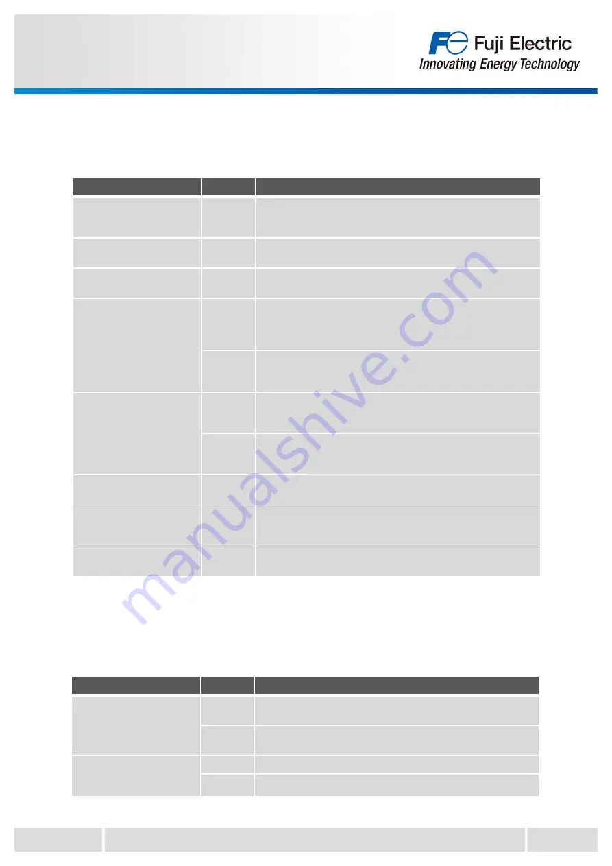
2.2 Electrical characteristics
2.2.1 Main circuit
2-4
Term
Symbol
Description
Collector Current at off
signal input
I
CES
Leakage current when specified voltage is applied between the
collector and emitter and all input signals are "H" (=all IGBTs are
turned-off).
Collector-Emitter saturation
voltage
V
CE(sat)
Voltage drop between the collector and emitter when gate input
signal is "L"(=IGBT is turned-on).
Forward voltage of FWD
V
F
Voltage drop across the FWD at defined forward current at input
signal is "H" (=IGBT is turned of).
Turn-on time
t
on
The time from when the input signal drop below the input
threshold value
V
inth(on)
until the collector current of IGBT become
above 90% of predetermined current.
Refer to Figure 2-1.(page 2-7)
t
d(on)
The time from when the input signal drop below the input
threshold value
V
inth(on)
until the collector current of IGBT become
above 10% of predetermined current. Refer to Figure 2-1.
Turn-off time
t
off
The time from when the input signal rise above the input
threshold value
V
inth(off)
until the collector current of IGBT become
10% of predetermined current. Refer to Figure 2-1.
t
d(o
ff
)
The time from when the input signal rise above the input
threshold value
V
inth(off)
until the collector current of IGBT become
90% of predetermined current. Refer to Figure 2-1.
Fall time
t
f
The time for the collector current to decrease from 90% to 10% of
the load current. Refer to Figure 2-1.
Reverse recovery time
t
rr
The time required for the reverse recovery current of the FWD to
disappear on the tangent line where it decreases. Refer to Figure
2-1.
Dead time
t
dead
On-off timing delay between upper and lower arm. Refer to Figure
2-6.
2.2.2 Control circuit
Term
Symbol
Description
Supply current of pre-driver
I
ccp
Current flows between
V
CC
terminal and GND of upper arm
control power supply
I
ccn
Current flows between
V
CC
terminal and GND of lower arm
control power supply
Input signal threshold
voltage
V
inth(on)
Input voltage which IPM can detect as ON signal.
V
inth(off)
Input voltage which IPM can detect as OFF signal.


