ZONE 1
1
4
2
3
5
6
7
8
0
ENTER
ESC
#
ZONE 2
ZONE 3
ZONE 4
TAMPER
FIRE
ZONE 6
ZONE 5
POWER
PART ARM
ARM
LOW BATT.
9
!
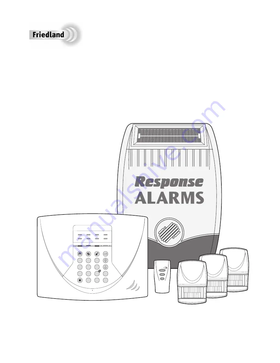
SA3 PLUS
with Telephone Dialler
Installation & Operating Manual
Страница 1: ...ZONE 1 1 4 2 3 5 6 7 8 0 ENTER ESC ZONE 2 ZONE 3 ZONE 4 TAMPER FIRE ZONE 6 ZONE 5 POWER PART ARM ARM LOW BATT 9 SA3 PLUS with Telephone Dialler Installation Operating Manual...
Страница 2: ...gh Environmental Officer to obtain full details of your area s requirements SYSTEM SECURITY This system has been designed to both detect intruders and act as a strong deterrent to would be intruders w...
Страница 3: ...formation 15 Positioning the Solar Siren 15 Installing and Configuring the Solar Siren 16 Power up of the Solar Siren 17 Testing the Solar Siren 17 EXTERNAL CONNECTIONS 18 TESTING THE SYSTEM 18 Initia...
Страница 4: ...d unless the clamshell is unopened and intact EXTENDING THE ALARM SYSTEM The following additional accessories are available to enhance your system and provide further protection and a higher level of...
Страница 5: ...fully armed until after the Entry Exit delay period has expired When a detector on a Delay Armed zone is triggered an alarm condition will not be triggered until after the Entry Exit period has elapse...
Страница 6: ...ame frequency If it is planned to operate the jamming detection feature we recommend that the system is monitored for false jamming alarms for at least 2 weeks prior to leaving the Jamming Detection f...
Страница 7: ...m system may be extended to provide even greater protection by fitting additional PlR Movement Detectors and Magnetic Contact Detectors as required PLANNING AND EXTENDING YOUR WIREFREE ALARM SYSTEM LE...
Страница 8: ...E REMOTE CONTROL 1 Remove the rear cover by undoing the small screw on the rear of the Remote Control and keeping it safe for later 2 Select and record in the Alarm Record section of this manual a ran...
Страница 9: ...rotected door or passing through an area protected by a PIR movement detector when the system is armed 5 The Control Panel must be located within reach of a mains socket 6 If the telephone voice diall...
Страница 10: ...s to both back up batteries and refit batteries Battery 1 left Red lead to ve battery terminal Blue lead to ve battery terminal Battery 2 right Blue lead to ve battery terminal Black lead to ve batter...
Страница 11: ...button is pressed LED ON 1 House Code DIP Switch On Up LED OFF 0 House Code DIP Switch Off Down b Press to save the new setting and return to programming mode c Press to return to programming mode wit...
Страница 12: ...h the system House Code and are mounted within effective radio range of the Control Panel The PIR Detector is powered by a PP3 Alkaline battery which under normal conditions will have an expected life...
Страница 13: ...of the fixing holes on the wall 4 Fix the rear cover to the wall using the two 18mm No 4 screws and 25mm wall plugs a 5mm hole will be required for the wall plugs Do not over tighten the fixing screws...
Страница 14: ...the detector to stabilise before commencing testing 1 Put the Control Panel into Walk Test mode by pressing on the Control Panel The Panel will beep and the Zone 1 LED will illuminate 2 Walk into and...
Страница 15: ...tion selected for the Magnetic Contact detector is within effective range of the Control Panel It is recommended that prior to installation the detector is configured and tested with the Control Panel...
Страница 16: ...ectors slide onto either side of the circuit board 10 Fit the battery cover into position on the Detector TESTING THE MAGNETIC CONTACT DETECTORS Ensure that the system is in Test mode see page 18 1 Pu...
Страница 17: ...unted on a sound flat surface so that the rear tamper switch is not activated when mounted Ensure that the tamper switch does not fall into the recess between brick courses as this could prevent the s...
Страница 18: ...ews holding the DIP Switch Cover in place and remove the cover 8 Under the cover you will find a series of 9 DIP switches Note When the Solar Siren is viewed as shown above Solar panel at top the DIP...
Страница 19: ...epeatedly during installation and testing as this will rapidly drain the battery It is recommended that the Siren be left for at least a day in order to charge the battery before the system is Armed 2...
Страница 20: ...is recommended that the system is tested at regular intervals not exceeding 3 months With the system in Standby Mode with the Power LED ON Press The Arm and Part Arm LEDs will flash The system is now...
Страница 21: ...ate that it has switched into normal operating mode IMPORTANT After changing the batteries and refitting in position the Solar Siren must be put back into normal Operating Mode otherwise the siren wil...
Страница 22: ...rned OFF Press to save the new User Access code and return to programming mode Press to return to programming mode without saving SYSTEM HOUSE CODE Press The Zone LEDs 1 6 Fire and Tamper LEDs will il...
Страница 23: ...nute 2 2 minutes 3 3 minutes 4 5 minutes 5 10 minutes Press the key corresponding to the required alarm period the corresponding zone LED will illuminate as the setting is changed Note When set to No...
Страница 24: ...ing OFF Press The zone 1 LED will illuminate to indicate the current Jamming Detector status LED ON Jamming Detection enabled LED OFF Jamming Detection disabled Press to change the setting to the oppo...
Страница 25: ...l Attack PA Zone 2 LED Intruder Zone 3 LED 24 Hour Intruder Zone 4 LED Fire Zone 5 LED Test Enter the key corresponding to the required operating mode the corresponding zone LED will illuminate as the...
Страница 26: ...cate the active status of telephone numbers 1 4 in the routing sequence LEDs for telephone numbers disabled will be OFF LED ON Telephone number enabled LED OFF Telephone number disabled To change the...
Страница 27: ...tart beeping with the beep rate increasing in steps as the delay expires If the system has not been Disarmed when the Entry Delay expires a Full Alarm condition will be initiated If a Full Alarm condi...
Страница 28: ...n the system will automatically reset or until the system is Disarmed from the Remote Control or Control Panel The Tamper LED on the Control Panel will flash to indicate the Tamper Alarm has been acti...
Страница 29: ...ector has a low battery status it will be indicated on the LOW BAT LED on the Control Panel LED ON Magnetic Contact LED Flashing PIR When a low battery indicator is activated the device will continue...
Страница 30: ...e power up battery to ensure that the Unit receives sufficient power until the solar panel can recharge the main battery 3 The main rechargeable battery has a typical life of 3 4 years and needs no ma...
Страница 31: ...Access Codes and Installer Access Code below User Access Code System House Code Use the above diagram to record your House Code e g Voice Dialler Phone Numbers Phone Number 1 Phone Number 2 Phone Num...
Страница 32: ...lose to metal objects 3 Detector battery low Replace detector battery Detection Zone triggered LED flashing but no alarm is sounding 1 Entry Exit delay still running and not yet expired 2 Alarm durati...
Страница 33: ...battery Magnetic Contact Detector not working 1 Ensure batteries are connected with correct polarity 2 Ensure battery connections are good 3 Ensure House Code is correctly set 4 Ensure DIP switches 9...
Страница 34: ...Code of Practice on Noise from Intruder Alarms 1981 you should carry out the following procedures within 48 hours of Intruder Alarm installation 1 Notify your local police station in writing that an I...
Страница 35: ...aterials and workmanship Understandably if the product has not been installed operated or maintained in accordance with the instructions has not been used appropriately or if any attempt has been made...
Страница 36: ...arm message Rings up to 4 telephone numbers 6 Zones Part Arm Facility Instant or Delayed Alarm Zones Programmable Entry Exit Delay Entry Exit Delay Warning selectable Internal piezo siren Connections...