


Chapter 19 Pulse-Width Modulator (S12PWM8B8CV1)
MC9S12XE-Family Reference Manual , Rev. 1.19
702
Freescale Semiconductor
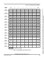
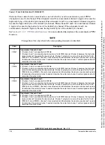
There are three control bits for concatenation, each of which is used to concatenate a pair of PWM
channels into one 16-bit channel. When channels 6 and 7are concatenated, channel 6 registers become the
high order bytes of the double byte channel. When channels 4 and 5 are concatenated, channel 4 registers
become the high order bytes of the double byte channel. When channels 2 and 3 are concatenated, channel
2 registers become the high order bytes of the double byte channel. When channels 0 and 1 are
concatenated, channel 0 registers become the high order bytes of the double byte channel.
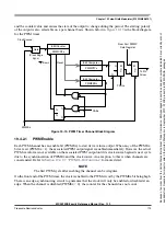
See
Section 19.4.2.7, “PWM 16-Bit Functions”
for a more detailed description of the concatenation PWM
Function.
NOTE
Change these bits only when both corresponding channels are disabled.
Field
Description
7
CON67
Concatenate Channels 6 and 7
0 Channels 6 and 7 are separate 8-bit PWMs.
1 Channels 6 and 7 are concatenated to create one 16-bit PWM channel. Channel 6 becomes the high order
byte and channel 7 becomes the low order byte. Channel 7 output pin is used as the output for this 16-bit
PWM (bit 7 of port PWMP). Channel 7 clock select control-bit determines the clock source, channel 7 polarity
bit determines the polarity, channel 7 enable bit enables the output and channel 7 center aligned enable bit
determines the output mode.
6
CON45
Concatenate Channels 4 and 5
0 Channels 4 and 5 are separate 8-bit PWMs.
1 Channels 4 and 5 are concatenated to create one 16-bit PWM channel. Channel 4 becomes the high order
byte and channel 5 becomes the low order byte. Channel 5 output pin is used as the output for this 16-bit
PWM (bit 5 of port PWMP). Channel 5 clock select control-bit determines the clock source, channel 5 polarity
bit determines the polarity, channel 5 enable bit enables the output and channel 5 center aligned enable bit
determines the output mode.
5
CON23
Concatenate Channels 2 and 3
0 Channels 2 and 3 are separate 8-bit PWMs.
1 Channels 2 and 3 are concatenated to create one 16-bit PWM channel. Channel 2 becomes the high order
byte and channel 3 becomes the low order byte. Channel 3 output pin is used as the output for this 16-bit
PWM (bit 3 of port PWMP). Channel 3 clock select control-bit determines the clock source, channel 3 polarity
bit determines the polarity, channel 3 enable bit enables the output and channel 3 center aligned enable bit
determines the output mode.
4
CON01
Concatenate Channels 0 and 1
0 Channels 0 and 1 are separate 8-bit PWMs.
1 Channels 0 and 1 are concatenated to create one 16-bit PWM channel. Channel 0 becomes the high order
byte and channel 1 becomes the low order byte. Channel 1 output pin is used as the output for this 16-bit
PWM (bit 1 of port PWMP). Channel 1 clock select control-bit determines the clock source, channel 1 polarity
bit determines the polarity, channel 1 enable bit enables the output and channel 1 center aligned enable bit
determines the output mode.
Because
of
an
order
from
the
United
States
International
Trade
Commission,
BGA-packaged
product
lines
and
part
numbers
indicated
here
currently
are
not
available
from
Freescale
for
import
or
sale
in
the
United
States
prior
to
September
2010:
S12XE
products
in
208
MAPBGA
packages


