


Chapter 19 Pulse-Width Modulator (S12PWM8B8CV1)
MC9S12XE-Family Reference Manual , Rev. 1.19
696
Freescale Semiconductor
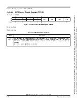
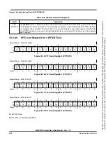
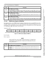
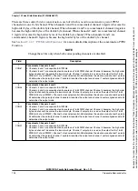
19.3.2.1
PWM Enable Register (PWME)
Each PWM channel has an enable bit (PWMEx) to start its waveform output. When any of the PWMEx
bits are set (PWMEx = 1), the associated PWM output is enabled immediately. However, the actual PWM
0x0018
PWMPER4
R
Bit 7
6
5
4
3
2
1
Bit 0
W
0x0019
PWMPER5
R
Bit 7
6
5
4
3
2
1
Bit 0
W
0x001A
PWMPER6
R
Bit 7
6
5
4
3
2
1
Bit 0
W
0x001B
PWMPER7
R
Bit 7
6
5
4
3
2
1
Bit 0
W
0x001C
PWMDTY0
R
Bit 7
6
5
4
3
2
1
Bit 0
W
0x001D
PWMDTY1
R
Bit 7
6
5
4
3
2
1
Bit 0
W
0x001E
PWMDTY2
R
Bit 7
6
5
4
3
2
1
Bit 0
W
0x001F
PWMDTY3
R
Bit 7
6
5
4
3
2
1
Bit 0
W
0x0010
PWMDTY4
R
Bit 7
6
5
4
3
2
1
Bit 0
W
0x0021
PWMDTY5
R
Bit 7
6
5
4
3
2
1
Bit 0
W
0x0022
PWMDTY6
R
Bit 7
6
5
4
3
2
1
Bit 0
W
0x0023
PWMDTY7
R
Bit 7
6
5
4
3
2
1
Bit 0
W
0x0024
PWMSDN
R
PWMIF
PWMIE
0
PWMLVL
0
PWM7IN
PWM7INL
PWM7ENA
W
PWMRSTRT
1. Intended for factory test purposes only.
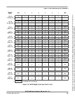
Register
Name
Bit 7
6
5
4
3
2
1
Bit 0
= Unimplemented or Reserved
Figure 19-2. PWM Register Summary (Sheet 3 of 3)
Because
of
an
order
from
the
United
States
International
Trade
Commission,
BGA-packaged
product
lines
and
part
numbers
indicated
here
currently
are
not
available
from
Freescale
for
import
or
sale
in
the
United
States
prior
to
September
2010:
S12XE
products
in
208
MAPBGA
packages


