


Chapter 5 External Bus Interface (S12XEBIV4)
MC9S12XE-Family Reference Manual Rev. 1.19
Freescale Semiconductor
253
5.4.3
Accesses to Port Replacement Registers
All read and write accesses to PRR addresses take two bus clock cycles independent of the operating mode.
If writing to these addresses in emulation modes, the access is directed to both, the internal register and
the external resource while reads will be treated external.
The XEBI control registers also belong to this category.
5.4.4
Stretched External Bus Accesses
In order to allow fast internal bus cycles to coexist in a system with slower external resources, the XEBI
supports stretched external bus accesses (wait states) for each external address range related to one of the
4 chip select lines individually.
This feature is available in normal expanded mode and emulation expanded mode for accesses to all
external addresses except emulation memory and PRR. In these cases the fixed access times are 1 or 2
cycles, respectively.
Stretched accesses are controlled by:
1. EXSTR1[2:0] and EXSTR0[2:0] bits in the EBICTL1 register configuring a fixed amount of
stretch cycles individually for each CSx line in MMCCTL0
2. Activation of the external wait feature for each CSx line MMCCTL0 register
3. Assertion of the external EWAIT signal when at least one CSx line is configured for EWAIT
The EXSTRx[2:0] control bits can be programmed for generation of a fixed number of 1 to 8 stretch
cycles. If the external wait feature is enabled, the minimum number of additional stretch cycles is 2. An
arbitrary amount of stretch cycles can be added using the EWAIT input.
EWAIT needs to be asserted at least for a minimal specified time window within an external access cycle
for the internal logic to detect it and add a cycle (refer to electrical characteristics). Holding it for additional
cycles will cause the external bus access to be stretched accordingly.
Write accesses are stretched by holding the initiator in its current state for additional cycles as programmed
and controlled by external wait after the data have been driven out on the external bus. This results in an
extension of time the bus signals and the related control signals are valid externally.
Read data are not captured by the system in normal expanded mode until the specified setup time before
the RE rising edge.
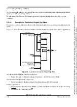
ECLK phase
...
high
low
high
low
high
low
...
ADDR[22:20] / ACC[2:0]
...
addr 0
acc 0
addr 1
acc 1
addr 2
acc 2
...
ADDR[19:16] / IQSTAT[3:0] ...
iqstat -1
iqstat 0
iqstat 1
...
ADDR[15:0] / IVD[15:0]
...
?
ivd 0
x
...
DATA[15:0] (internal read)
...
?
z
z
(write) data 1
z
...
DATA[15:0] (external read)
...
?
z
data 0
(write) data 1
z
...
RW
...
1
1
0
0
1
1
...
Table 5-18. Interleaved Read-Write-Read Accesses (1 Cycle) (continued)
Because
of
an
order
from
the
United
States
International
Trade
Commission,
BGA-packaged
product
lines
and
part
numbers
indicated
here
currently
are
not
available
from
Freescale
for
import
or
sale
in
the
United
States
prior
to
September
2010:
S12XE
products
in
208
MAPBGA
packages


