


Chapter 15 Inter-Integrated Circuit (IICV3) Block Description
MC9S12XE-Family Reference Manual , Rev. 1.19
582
Freescale Semiconductor
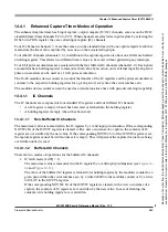
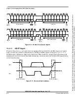
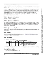
Figure 15-5. SCL Divider and SDA Hold
The equation used to generate the divider values from the IBFD bits is:
SCL Divider = MUL x {2 x (s [(SCL_Tap -1) x tap2tap] + 2)}
The SDA hold delay is equal to the CPU clock period multiplied by the SDA Hold value shown in
. The equation used to generate the SDA Hold value from the IBFD bits is:
SDA Hold = MUL x {s [(SDA_Tap - 1) x tap2tap] + 3}
The equation for SCL Hold values to generate the start and stop conditions from the IBFD bits is:
SCL Hold(start) = MUL x [scl (SCL_Tap - 1) x tap2tap]
SCL Hold(stop) = MUL x [sc (SCL_Tap - 1) x tap2tap]
NOTE
A master SCL divider period can be prolonged at higher internal bus
frequencies. This happens when the internal bus cycle length becomes equal
to a pad delay. The SCL input is used for clock arbitration of multiple
masters. Thus after each SCL edge is internally driven an extra bus period
is counted before the pad level is attained, allowing the next toggle. This has
the effect of extending the SCL Divider values in
and IBC[7:0] = 0x00 to 0x0F.
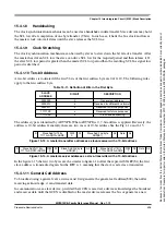
Table 15-7. IIC Divider and Hold Values (Sheet 1 of 6)
IBC[7:0]
(hex)
SCL Divider
(clocks)
SDA Hold
(clocks)
SCL Hold
(start)
SCL Hold
(stop)
MUL=1
00
20
7
6
11
01
22
7
7
12
02
24
8
8
13
03
26
8
9
14
04
28
9
10
15
05
30
9
11
16
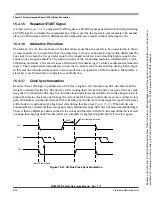
SDA
SCL
START condition
STOP condition
SCL Hold(start)
SCL Hold(stop)
Because
of
an
order
from
the
United
States
International
Trade
Commission,
BGA-packaged
product
lines
and
part
numbers
indicated
here
currently
are
not
available
from
Freescale
for
import
or
sale
in
the
United
States
prior
to
September
2010:
S12XE
products
in
208
MAPBGA
packages


